
Ducati Diavel Service Manual: Removing the flywheel - generator assembly
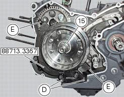
Use the tool 88713.3367 Fixed to the m10 side stand fixing holes (d).
Secure the tool to the flywheel with the screws (e).
Unscrew the alternator-flywheel retaining nut (15).
Warning
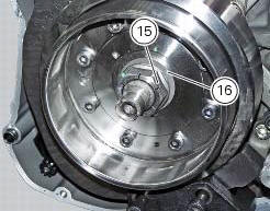
While unscrewing the nut, apply axial pressure to the socket to avoid damage or injury in the event of the wrench suddenly slipping off the nut.
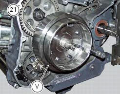
Remove the nut (15), the washer (16) and the flywheel assembly (v) with the driven gear (21) from the crankshaft.
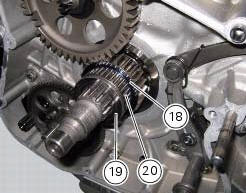
Remove the inner race (19), the needle roller bearing (20) and the washer (18).
Important
Check the race (19), the needle roller bearing (20) and the inner washer (18) for wear. Renew if worn.
 Disassembly of the generator cover
Undo the three stator retaining screws (25) and the two retaining screws (9)
of the two cable grommet bracket (10) from
inside the generator cover.
Remove the stator (2) and the cable grommet br ...
 Overhaul of the flywheel-alternator assembly
Examine the inner part of alternator rotor (24) for signs of damage. Check
that the starter clutch is working properly and
that the needle races do not show signs of wear or damage of any kind. If ...
Other materials:
Indicator cons. Avg - average fuel consumption
This function indicates the "average" fuel consumption.
The calculation is made considering the quantity of fuel used and the km
travelled since the last trip 1 reset. When trip 1
is reset, the value is set to zero and the first available value is shown on the
display 10 seconds after the re ...
Stored lap display function
This function displays the stored laps.
To access the function it is necessary to view the "setting" menu page 48, using
button (1, fig. 14) ?"" or (2, fig.
14) ?" " select the "lap" function and
press the reset button
(12, fig. 12) To go to next pag ...
Final drive
Circlip
Nut
Washer
Nut
Rear sprocket flange
Cush drive bush
Inner ring
Chain
Spacer
Chain cover
Screw
Nut
Lock washer
Front sprocket
Spacer
O-ring
Rear sprocket
Spare parts catalogue
Diavel abs gearbox
Diavel abs rear wheel axle
Diavel carbon
abs
gearbo ...