
Ducati Diavel Service Manual: Removal of the clutch
Note
For clarity, the figures show the engine removed from the frame.
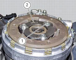
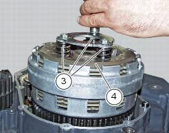
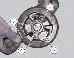
Undo the fixing screws (1) and remove the ring (2) and the springs (3) from the pressure plate (4).
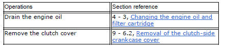
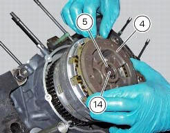
Slide the pressure plate (4) paying attention to the circlips (6).
Remove the clutch control pin (14) and the bearing (5).
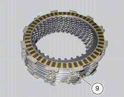
Remove the clutch plates. When removing the discs (9), keep them paired in the assembly order and set them aside tied together, if necessary.
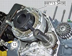
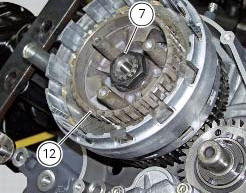
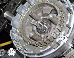
Restrain the clutch centre (12) using service tool 88713.3408 And remove the centre nut (7).
Withdraw the belleville washer (8) and slide out the clutch drum (12).
Slide the
Withdraw the belleville washer (8) and slide out the clutch drum (12).
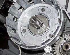
Slide the spacer (13).
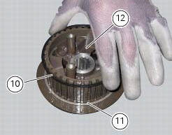
Withdraw the belleville washer (10) and flat ring (11) from the clutch centre (12).
 Description of the clutch assembly
The clutch is disengaged by a drive unit consisting of a thrust piston (c)
accommodated inside a small cap mounted to
the generator cover. This piston (c) pushes a pushrod (b), which runs through
...
 Checking and overhauling the components
Clearance between the clutch drum and friction plates
Insert a friction plate (e) in the clutch drum (f) and measure the clearance
(s) with a feeler gauge.
Clearance "s" must not exceed 0.6 Mm.
...
Other materials:
Reassembly of rear shock absorber - rocker arm - linkage assembly
Once the needle roller bearings (9) have been removed from the rocker arm
(18), upon reassembly fit a new needle roller
bearing (9) on drift part no. 88713.1071 And lubricate with recommended grease.
Support the rocker arm and drive the needle roller bearings into the rocker arm
bore until t ...
Instrument panel on handlebar
Lcd.
Neutral light n (green). Illuminates when the gearbox is in neutral.
High beam light (blue).
It turns on to indicate that the high beam lights are on.
Engine oil pressure light
(red).
Illuminates when engine oil pressure is too low. It must turn
on at key-on, but ...
Clutch cover
Clutch-side crankcase cover
Screw
Screw
Oil level sight glass
Screw
Plate
Bush
Sealing ring
Shim washer
Circlip
O-ring
Locating bush
O-ring
Plug
Sealing washer
Screw
Plug
Panel
Spare parts catalogue
Diavel abs clutch-side crankcase cover
Diavel carbon
a ...