
Ducati Diavel Service Manual: Removing of the front sprocket
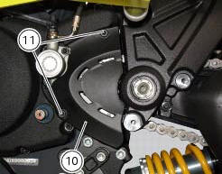
Undo the screws (11) and remove the chain cover (10).
Loosen the chain (sect. 4 - 3, Adjusting the chain tension).
Remove the chain with the tool code 88713.1344.
The tool is composed of a holder (a), punch (b), body (c) and two wrenches (d) and (e).
Fit the link to be opened into the holder (a).
Fit a punch (b) into the body (c) and manually unscrew the screw until the punch no longer protrudes.
Fit the holder (a) and link into the body (c).
Manually turn the screw (f) on body (c) so that the punch (b) locates against the pin, taking care that they are aligned with each other.
Fit hex wrench (d) into the hexagonal part of the body (c) and wrench (e) onto the bolt.
Turn the bolt (f) clockwise to push out the pin.
Remove the chain.
Engage a low gear and unscrew the nut (12).
Remove the nut (12) and the safety washer (13) on the pinion.
Remove the engine pinion (14) from the gearbox secondary shaft.

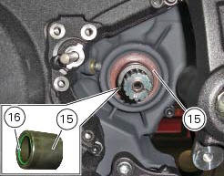
Remove the spacer (15) with o-ring (16) from the gearbox secondary shaft.
Important
The o-ring (16) must be renewed on reassembly.
 Inspecting the final drive
To check the wear of the final drive, visually check the pinion (14) and
sprocket (17). If the teeth are found to worn as
shown in the figure (dotted line), the sprocket must be renewed.
T ...
 Refitting the front sprocket
Grease the o-ring (16) and install it on the front sprocket spacer (15).
Fit the spacer, from the o-ring side, on the secondary shaft and drive it fully
home against the inner ring of the bearing ...
Other materials:
Riding mode customisation
This function customises each riding style.
To access the function it is necessary to view the "setting"
menu page 48, using button (1, fig. 14) ?
or (2, fig. 14)
? select the "riding mode" function
and press the
reset button (12, fig. 12) To go to next page.
W ...
Low battery level
The activation of this (amber yellow) "warning" indicates
that the status of the battery vehicle is low.
It is activated when the battery voltage is . 11.0 Volt.
Note
In this case, ducati recommends charging the battery
as soon as possible with the specific device, as it is possibl ...
Protective apparel
Always wear a helmet. Most motorcycle accident fatalities
are due to head injuries.
For safety eye protection, gloves, and high top, sturdy boots
should also be worn.
The exhaust system becomes very hot during operation,
never touch the exhaust system. Wear clothing that fully
covers your ...