
Ducati Diavel Service Manual: Refitting the cylinder heads pulleys/fixed tensioners
Check that the keyway on the end of the camshaft is in good condition and without burrs.
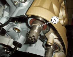
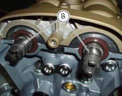
Fit a woodruff key (b) in the keyway of each camshaft.
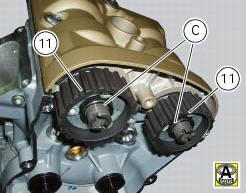
Fit the pulley (11) on the camshaft, inserting the woodruff key in the in the slot (c) in the pulley.
Apply the recommended grease to the threads on the end of the camshaft.
Repeat the procedure on the other camshaft.
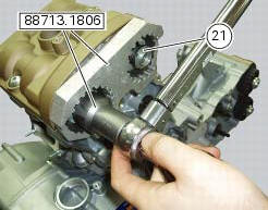
Insert the tool code 88713.1806 Into the pulleys to prevent rotation.
Apply the recommended grease to the mating face of the nut (21).
Fit the nut (21).
Carry out the same operations on the other camshaft.
Important
Always fit new nuts on reassembly.
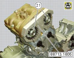
Using the bush supplied with tool with part no. 88713.1806 And a torque wrench, tighten the ring nuts (21) to the specified torque of 71 nm (min. 64 Nm - max. 78 Nm) (sect. 3 - 3, Engine torque settings).
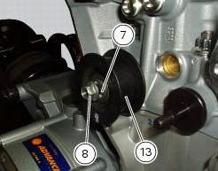
Insert the fixed tensioners (13), with bearings and washers (7), into the cylinder head pins and tighten the nuts (8) to a torque of 25 nm (min. 22 Nm - max. 28 Nm) (sect. 3 - 3, Engine torque settings).
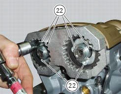
Undo the locking screws (22) of the pulleys, turning them anti-clockwise through 90 +/- 5.
Check that the pulleys have no end float and can rotate freely at all points along the full length of the slots.
 Reassembly of the timing pulleys
Fit the pulley (11) on the flange (24), aligning the timing mark (d) on the
pulley with the timing mark on the (e) on the
flange.
Install the washer (23) up against the pulley, aligning the timi ...
 Refitting the timing belts
Rotate the pulleys on the timing belt driveshaft until the timing mark on the
outer roller is aligned with the mark on the
clutch-side crankcase cover.
In this condition, the horizontal cylinder ...
Other materials:
Riding mode set indication
This function indicates the "riding style" set for the vehicle.
Three "riding modes" are available: sport, touring and
urban.
Each riding mode can be changed using the "riding
mode" function.
Note
The background of the riding mode (sport, touring
or urban) i ...
Deactivating the service indication on the dashboard
The message "serv" is displayed on the dashboard, indicating that the
motorcycle should be serviced in accordance with
the programmed maintenance plan. This indication is activated after the first
1000 km and thereafter at intervals of
12000 km.
After the scheduled service has been carried ...
Key-on/key-off using the pin code (immobilizer release)
Key-on can be performed by pressing the button (7) on the
hands free lock (1, fig. 77) Without the presence of the keys
(3, fig. 77) And (4, fig. 77) And entering the pin code on the
dashboard.
Key-off can be performed by pressing the button (6) on the
handlebar / hands free key (7) / engine ...