
Ducati Diavel Service Manual: Removing of the abs control unit
Drain the hydraulic fluid that is inside the front and rear braking system tubes by disconnecting them from the master cylinder and the calliper (sect. 4 -3, Changing the brake fluid).
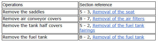
Disconnect the connector (a) of the abs control unit (6).
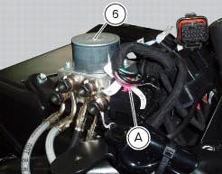
Loosen the screws (16) that retain the abs control unit support (12) and remove it from the vehicle.
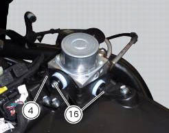
Undo the four special screw (17) fixing the pipes (10), (9), (8) and (7), on the abs control unit (6), removing the gaskets (11).
Warning
Every time that gaskets (11) are removed, they must be replaced with new gaskets (11).
Important
Do not open the abs control unit: if it is faulty, replace it.
Note
If it is necessary to replace one or more pipes, follow the instructions indicated in paragraph "flexible wiring/hoses positioning" of this section.
 Replacing the rear phonic wheel sensor
Disconnect the rear abs sensor (5) connector (c) from the main electric
wiring.
Open all the retainer clamps of the rear abs sensor cable (5): refer to table of
sect. 7 - 6, Flexible wiring ...
 Refitting the abs control unit
If the brake hoses (7), (8), (9) and (10) on the abs control unit are changed
or removed, ensure that the fittings on the
control unit are positioned correctly.
Warning
If incorrectly positioned, ...
Other materials:
Refitting the silencer
Position the silencer guard (41) and fix it by starting the screws (40).
Tighten the screws (40) to a torque of 8 nm +/- 10% (sect. 3 - 3, Frame torque
settings).
Insert the silencer (4) into the central exhaust pipe (26), and fix it to the
vehicle by starting the screw (1).
Hold the ...
Ignition coils
Introduction
The engine control system of the diavel includes two ignition coils: one for
the horizontal cylinder and one for the vertical
cylinder. These coils are installed directly in the spark plug wells. A diode is
installed on the secondary winding inside the
coil, which prevents the un ...
Removing of the front sprocket
Undo the screws (11) and remove the chain cover (10).
Loosen the chain (sect. 4 - 3, Adjusting the chain tension).
Remove the chain with the tool code 88713.1344.
The tool is composed of a holder (a), punch (b), body (c) and two wrenches (d)
and (e).
Fit the link to be opened into th ...