
Ducati Diavel Service Manual: Airbox - throttle body
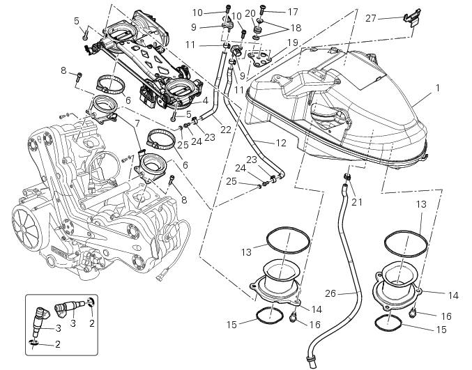
- Airbox
- O-ring
- Injector
- Throttle body assembly
- Screw
- Clamp
- Intake manifold
- Screw
- Pressure sensor
- Screw
- Clamp
- Hose
- Sealing washer
- Intake manifold
- Sealing washer
- Screw
- Screw
- Spacer
- Bracket
- Rubber pad
- Clamp
- Hose
- Clamp
- Union
- Washer
- Hose
- Cable grommet
- Spare parts catalogue
- Diavel abs throttle body
- Diavel abs Air intake - oil breather
- Diavel abs fuel system
- Diavel carbon abs throttle body
- Diavel carbon abs air intake - oil breather
- Diavel carbon abs fuel system
Important
Bold reference numbers in this section identify parts not shown in the figures alongside the text, but which can be found in the exploded view diagram.
 Refitting the fuel tank
If the fuel tank has been disassembled into its component parts, reposition
all the parts as shown in the exploded view.
In particular:
tighten the screws (13) to a torque of 5 nm +/-10% (sect. ...
 Removal the airbox and throttle body
Loosen the screws (a) and remove the plate (b) that fixes the main wiring to
the airbox.
Undo the screws (17) and remove the air pressure sensors (9) with the support
(19).
Release t ...
Other materials:
Footrest brackets
Rubber footrest
Right front footrest
Pin
Spring
Circlip
Right footrest bracket
Screw
Washer
O-ring
Bush
Rubber pad
Right rear footrest
Pin
Ball
Spring
Plate
Screw
Vibration damper mount
Special screw
Front lh footrest
Left footrest bracket
Left rear f ...
Reassembly of the connecting rods
Before starting, check that the crankshaft main bearing journals and big-end
journals are free of burrs or evident signs of
machining: if necessary, clean the surfaces with very fine emery cloth and oil.
Check that the grooves are in perfect condition with no signs of forcing.
Clean the cra ...
Battery voltage indicator (battery)
This function describes the battery voltage indicator.
To access the function it is necessary to view the ""setting" menu", using
buttons (1) "s" or (2) "t" select the "battery"
function and press the reset button (3) to confirm.
The information will be displayed as follows:
if battery vol ...