
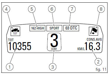
Ducati Diavel Owners Manual: Instrument panel on tank
- Menu 1 (tot, trip1, trip2, trip fuel).
- Menu 2 (cons.Avg., Cons., Speed avg, air and trip time) if active.
- Gear / neutral indication.
- Icon referred to the function below from menu 1.
- Indication of engine setting for the currently set riding style.
- Currently set riding style (riding mode).
- Indication of the intervention level of the dtc (traction control) for the currently set riding style.
- Icon referred to the function below from menu 2.
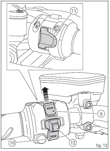
- Control button (fig. 12).
Button used to display and set instrument panel parameters
with the position  .
.
- Control switch (fig. 12).
Button used to display and set instrument panel parameters
with the position  .
.
- High-beam flasher button flash (fig. 12).
The high-beam flash button may also be used to for lap functions.
- Reset button (fig. 12).
The turn indicators off button may also be used for the reset/confirm function on the instrument panel and for activating the "riding style".
 Display background colour (automatic adjustment)
Instrument panel background colour is set automatically
according to exterior lighting conditions.
When sensor detects "poor lighting" (night), it switches to
black background mode; vic ...
 Tft - parameter setting/display
Warning
Any adjustments to the instrument panel must only be
carried out when the motorcycle is stationary. Never operate
the instrument panel controls while riding the motorcycle.
At the end of ...
Other materials:
Refitting the engine
Refitting is the reverse of removal.
Important
Apply recommended grease and tighten the special screws (6) to a torque of
60 nm +/- 5% (sect. 3 - 3, Frame torque
settings).
Tighten the nuts (3) to a torque of 48 nm +/- 5% (sect. 3 - 3, Frame torque
settings).
Warning
For the assembly seque ...
Frame torque settings
*Dynamic safety-critical point; tightening torque must be within nm +/-5%.
Note
For product specifications and symbols, refer to "product specifications"
(sect. 1 - 2). ...
Resetting turn indicators not possible - accessing dashboard menu not
possible
Fault codes
Dds: no fault code displayed
Dashboard: no fault code displayed
Location of connections and components
Location of left hand handlebar switchgear set connection.
Pin numbering for wiring harness side dashboard connector.
Checks
Test turn indicator reset button function. Wh ...