
Ducati Diavel Service Manual: Removal of the front brake system

Note
For the abs front braking system, also refer to sect. 7 - 5, Abs system operating information, sect. 7 - 6, System components, sect. 7 - 7, Abs components maintenance.
Undo the special screw (3), collect the sealing washers (4), and release the front brake master cylinder assembly (1) from the pipe.
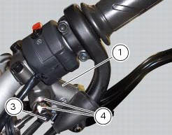
Tighten the screw (16) and slide the front brake pipe (13) from the bracket (17) on the yoke base.

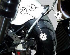
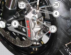
Loosen screw (c) to remove front brake hose (20) and the abs sensor cable (a) from hose clip (b).
Warning
While removing the front brake hose, if you damage the hose clip (b) you shall renew it (sect. 5 - 4, Removal of the front mudguard).
If hose is not fastened by hose clip (b), it might interfere with tyre under braking and provoke accidents.
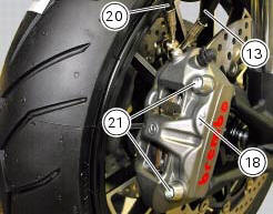
Unscrew the two fixing screws (21) of the left front brake calliper (9) to the fork leg.
Repeat the operation for the right brake calliper (18).
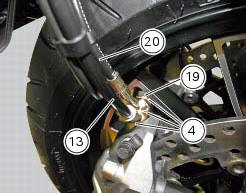
Undo the special screws (19) and (25) and collect, from both callipers, the sealing washers (4).
Detach the front brake callipers from the pipe (13) and (20).
Removal
 Maintenance operations
Warning
Brake fluid is corrosive and will damage paintwork. Avoid contact
with eyes and skin. In case of accidental contact, wash
the affected area with abundant running water and consult a doctor ...
 Removal of the brake discs
The front brake discs consist of an inner carrier, which is mounted to the
wheel, and an outer rotor. Both parts must be
changed together as a pair.
Remove the front wheel (sect. 7 - 1, Removal ...
Other materials:
Refitting the intake manifold and coolant union
Apply prescribed threadlocker to the fitting (12), start it with seal (24)
and tighten it to a torque of 2.5 Nm (min. 2 Nm -
max. 3 Nm) (sect. 3 - 3, Frame torque settings).
Install the pipe (b) and tighten the clamp (a) to the torque of 1 nm +/- 10%
(sect. 3 - 3, Engine torque settings).
...
Refitting the hands free
Reassembly is a reversal of the removal procedure: in particular apply
prescribed threadlocker to screws (2) and tighten
them to a torque of 20 nm +/- 10% (sect. 3 - 3, Frame torque settings).
If the hands free button has been previously removed, when refitting it insert
the spring (6) on pi ...
Guided diagnosis
Note
The on-screen icons used during this procedure are explained in a table at
the end of this section.
The dds diagnosis instrument guides the operator step-by-step through the
various diagnostic procedures,
providing descriptions and documentation for motorcycle components, wiring
diagra ...