
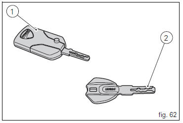
Ducati Diavel Owners Manual: Keys (fig. 62)
The owner receives a set of keys comprising:
- 1 Active key (1, fig. 62)
- 1 Passive key (2, fig. 62)
It contains the code used by the "hands free" system for the key-on, in different modes.
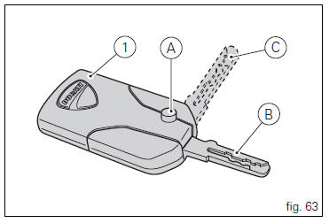
The active key (1, fig. 63) Is the one that is normally used: press button (a, fig. 63) To fully open the metal part, i.E.
Position (b, fig. 63). Holding depressed button (a, fig. 63) You can move the metal part and set it to the middle position (c, fig. 63); Once in place, release button to lock.
The metal part returns inside the grip by pushing it in.
The key contains a battery that must be replaced when the low key battery "warning" is displayed as soon as the instrument panel is turned on (fig. 64).
 Note
Note
In this case, replace the battery as soon as possible (page 88).
When the charge level goes below a certain limit, the key can only work in passive mode, like the passive key: in this case, the instrument panel will not display any message.
 Warning
Do not ride with the key (1 or 2, fig. 62) Inserted in the lock of the tank cap or in the seat lock as it could come out and represent a potential danger. Furthermore, if bumped, the key mechanism and the integrated circuit could be damaged.
Also riding in poor weather conditions with the key inserted could cause damage to its integrated circuit.
Do not leave the key on the motorcycle when washing it as it could be damaged, not being watertight.
 The immobilizer system
For additional antitheft protection, the motorcycle is
equipped with an immobilizer, an electronic system that
locks the engine automatically whenever the ignition switch
is turned off.
The grip ...
 Replacing the battery in the active key
Only use 3 volt cr 2032 lithium ion batteries.
Note
The keys do not need to be reprogrammed after
replacing the battery.
Remove the metal part of the battery.
Use a large sized coin to pry ope ...
Other materials:
Reassembly of the timing pulleys
Fit the pulley (11) on the flange (24), aligning the timing mark (d) on the
pulley with the timing mark on the (e) on the
flange.
Install the washer (23) up against the pulley, aligning the timing notch (f)
with the timing marks on the pulley and the
flange.
Insert the three screws (22) ...
Removal of the tool tray
To remove the tool tray unit from the lateral footrests, loosen the screws
(40) and remove the splashguard (20).
Undo the screws (15) and remove the cover (16).
Move the wiring branch from the seat (s) on the tool tray.
Loosen the screws (24) to remove the tool tray unit (23) from ...
Checking and adjusting timing belt tension
Note
The on-screen icons used during this procedure are explained in a table at
the end of this section.
Note
This operation, which is performed using the dds diagnosis instrument, has
the advantage that it can be carried out on
both timing belts with the engine still installed on the frame. ...