
Ducati Diavel Service Manual: Reassembling the water radiator unit
The procedure is the same for both radiators.
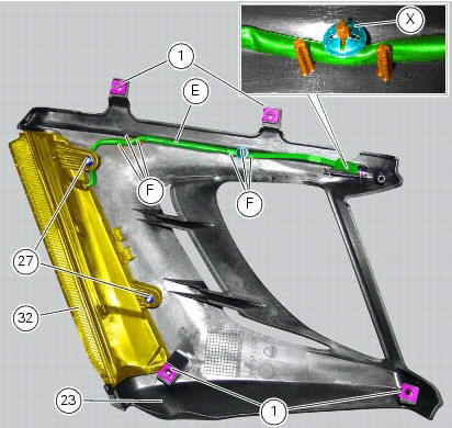
Check the presence of clips (1) at the positions of the external coolant radiator cover (23).
If removed, fit the front turn indicator (32) on the cover (23) and tighten the screws (27) to 2 nm +/- 10% (sect. 3 - 3, Frame torque settings).
Note
When fitting the turn indicator (32), make sure to arrange the indicator cable (e) behind the indicator retaining stud bolt.
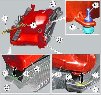
Arrange the right turn indicator cable (e) fitting it between the suitable pins (f) on the cover (23).
Fix the cable (e) inserting a retainer (x) on the pin (f) shown.
Note
Make sure to orient the retainer (x) as shown.
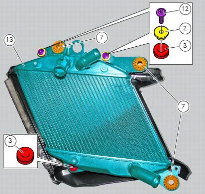
Fit the vibration dampers (7) and the vibration dampers (3) on the right coolant radiator (13) at the positions shown.
Insert the spacers with collar (2) onto the "upper" vibration dampers (3).
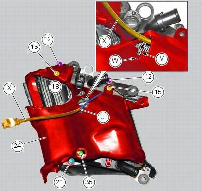
Fix the right coolant radiator (13) by starting the screws (12).
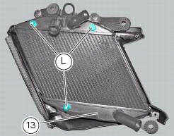
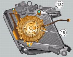
Position the right fan assembly (18) on the right coolant radiator (13), so that the holes in the assembly (18) match the protrusions (l) on the radiator (13).
Fit a rubber pad (u) as shown into the suitable hole in the internal cover of the right coolant radiator (24).
Note
For the rubber pad (u) to be installed correctly, the pin (m) must be fully out at the side opposite to insertion site.
Position the internal cover (24) as shown, making sure the tabs (n) and (o) of the right coolant radiator (23) external cover become engaged in the slots (q) and (r) of the internal cover (24).
Note
While positioning the internal cover (24), make sure to thread the right fan cable (x) into the opening (t) in the cover as shown.
Insert the right fan cable (x) into the recess (v) in the right coolant radiator internal cover (24).
Insert the small self-locking tie wrap (j) into the hole (w) in the cover (24) and use it to fix the cable (x).
Start the screw with a shorter collar (35), the screws with medium collar (15) and the screw with a taller collar (21) at the positions shown.
Tighten the screws (35), (15) and (21) and the screws (12) installed previously to a torque of 5 nm +/- 10% (sect. 3 - 3, Frame torque settings).
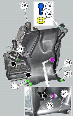
Start the screw (14) with washer (34) and tighten to a torque of 5 nm +/- 10% (sect. 3 - 3, Frame torque settings).
Tighten the screw (25).
Check the presence of four clips (31) on the internal cover (24) of the right radiator; the left radiator has two clips (31) only (shown).
On the right radiator only, check the presence of the plug (20) inserted from the internal side of the internal cover (24).
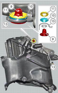
Insert the spacer with the collar (10) into the suitable hole in the right coolant radiator (13).
On the opposite side, insert the pin receptacle (9) into the spacer with collar (10) and fix it using the retainer (11) oriented as shown.
 Renewal of the cooling fan
Loosen the electro-fan retaining screws (15) and (17) and remove the
electro-fan (18) from the radiator.
Carry out the same procedure for the other radiator's electro-fan.
On refitting, positi ...
 Refitting the radiator
The reassembly procedure is the same for both radiators.
Check for the nuts with clips (8).
Refit the rh radiator (13) on the frame and tighten the screws (4) and (5)
with the spacers (6) to ...
Other materials:
Number plate light not working
Fault codes
Dds: no fault code displayed.
Dashboard: no fault code displayed.
Location of connections and components
Location of rear turn indicator and number plate light connection.
pin numbering for wiring harness side dashboard connector.
Checks
The number plate light receives p ...
Vehicle speed indicator
This function displays vehicle speed (km/h or mph depending on the set
measurement system).
The dashboard receives information about the actual speed and displays the
number increased by 5%.
Maximum speed displayed is 299 km/h (186 mph).
Over 299 km/h (186 mph) the display will show a s ...
Refitting the exhaust system
Refit the heat guard on the manifold (10) by tightening the nuts (9) to a
torque of 10 nm +/- 10% (sect. 3 - 3, Frame
torque settings).
Position the vertical exhaust manifold (22) on the vertical cylinder head
with the gasket (23).
Tighten the fixing nuts (21) to a torque of 10 nm +/- 1 ...