
Ducati Diavel Owners Manual: Replacing the battery in the active key
Only use 3 volt cr 2032 lithium ion batteries.
 Note
Note
The keys do not need to be reprogrammed after replacing the battery.
Remove the metal part of the battery.
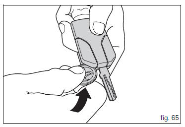
Use a large sized coin to pry open the shells of the plastic grip (2? coin) as shown in fig. 65.
 Important
Insert the coil only in the indicated point. Do not other use other objects inserted in points that are different than what is shown, as it could damage the integrated circuit and/ or the protective gasket.
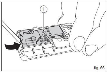
Once the plastic shells have been separated, remove the printed circuit board (1, fig. 66) Prying it up gently with a small flat screwdriver, as shown in the figure.
 Important
insert the point of the flat screwdriver just under the printed circuit board, being very careful not to damage it.
do not apply force on the battery or battery holder.
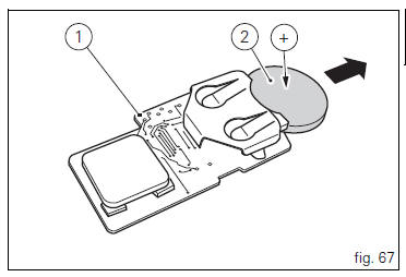
Remove the battery (2, fig. 67) From the printed circuit board (1, fig. 67) And replace it with a new one.
Pay attention to polarity: the positive pole (+) must face upward.
 Important
Only use the required type of battery.
Reinsert the printed circuit board (1, fig. 68) From the side with the battery (2, fig. 68) Into the plastic shell.
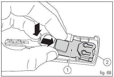
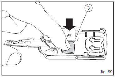
Apply slight pressure on the antenna (3, fig. 69) Of the printed circuit board until you hear a click.
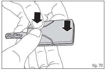
Align the two shells of the grip and press on the area indicated by the arrows (fig. 70) To reclose them.
Make sure that you hear a "click" upon closing and that the key is well closed.
 Keys (fig. 62)
The owner receives a set of keys comprising:
1 Active key (1, fig. 62)
1 Passive key (2, fig. 62)
It contains the code used by the "hands free" system for the
key-on, in different ...
 Duplicate keys
If you need any duplicate keys, contact the ducati service
network with all the keys you have left.
The ducati service centre will program all the new keys as
well as any keys you already have.
...
Other materials:
Parking
Park the stopped motorcycle on the side stand.
Turn the handle completely to the left or right.
If this operation is performed within 60 seconds after the
engine stop, the message "waiting for lock" (fig. 120) Will
appear on the display of the instrument panel for approx.
5 Seco ...
High beam flash not working - start/stop lap function not working
Fault codes
Dds: no fault code displayed.
Dashboard: no fault code displayed.
Wiring diagram
Db dashboard connection, s high beam flash button. 7 Orange - o, 1
red/blue - r/b.
Location of connections and components
Location of left hand handlebar switchgear set connection.
Pin ...
Refitting the clutch master cylinder assembly
Insert the clutch master cylinder assembly (3) and the clamp (6) on the left
handlebar, so that the top mating faces
match the mark (z) on the handlebar as shown.
Couple terminal (6) to the clutch master cylinder control and fix them with
the screws (v).
Tighten the retaining screws ...