
Ducati Diavel Service Manual: Reassembling the clutch
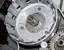
Position the spacer (13).
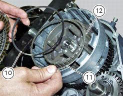
Fit the flat ring (11) and the belleville washer (10) on the clutch center (12), so that the convex side faces the clutch drum.
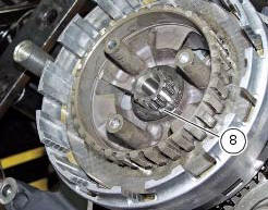
Locate the belleville washer (8).
Apply the prescribed grease to the thread of the gearbox primary shaft and the mating surface of nut (7), and fit it over belleville washer (8).
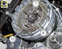
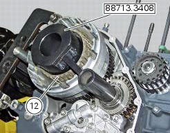
Lock the clutch center (12) by means of tool number 88713.3408 And tighten the retaining nut (7) to a torque of 190 nm (min. 180 Nm - max. 200 Nm) (sect. 3 - 3, Engine torque settings).
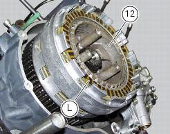
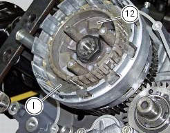
Install the clutch plates (9) in the following order: on the drum (12):
- A series of ten driving discs (l) alternately to new driven discs (i) thickness 2 mm;
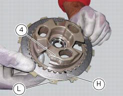
On the pressure plate (4):
- One driven disc (h), 2 mm thick;
- A driving disc (l).
Insert the control pin (14) in the bearing (5) and the latter in the gearbox primary shaft.
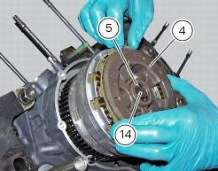
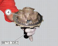
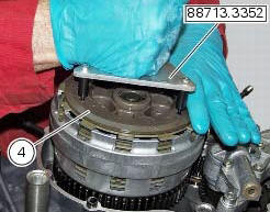
Place the pusher plate (4) with the two discs on the centring tool part no. 88713.3352.
Fit the pressure plate (4).
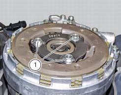
Insert a spring (3) in each slot.
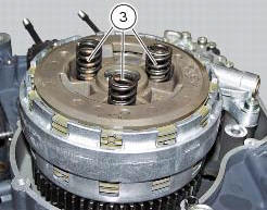
Position the o-ring (2).
Lubricate the thread of the screws (1) with oil.
Insert the screws (1).
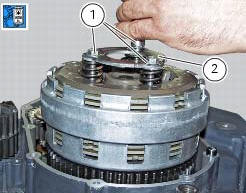
Tighten the screws (1) to a torque of 10 nm (min. 9 Nm - max. 11 Nm) (sect. 3 - 3, Engine torque settings).
 Checking and overhauling the components
Clearance between the clutch drum and friction plates
Insert a friction plate (e) in the clutch drum (f) and measure the clearance
(s) with a feeler gauge.
Clearance "s" must not exceed 0.6 Mm.
...
 Clutch cover
Clutch-side crankcase cover
Screw
Screw
Oil level sight glass
Screw
Plate
Bush
Sealing ring
Shim washer
Circlip
O-ring
Locating bush
O-ring
Plug
Sealing washer
Scr ...
Other materials:
Primary drive gears
Clutch drum/primary drive gears
Spacer
Threaded ring nut
Lock washer
Spare parts catalogue
Diavel abs clutch
Diavel abs connecting rods
Diavel carbon
abs
clutch
Diavel carbon
abs
connecting rods
Important
Bold reference numbers in this section identify parts not shown in th ...
Helmet cable
Note
Helmet cable (2, fig. 104) Can be found inside the tool
kit, see "tool kit and accessories" on page 141.
Pass the cable through the helmet and insert the end of the
cable in the pin (3, fig. 104). Leave the helmet hanging and
refit the seat to hold it in place.
Warning
Th ...
Refitting the rear suspension
Lubricate the thread and underside of the special screw (1).
Insert the lower side of the shock absorber into the swingarm and insert the
screw (1).
Tighten the screw (1) to a torque of 45 nm +/- 5% (sect. 3 - 3, Frame torque
settings).
Lubricate bushes (5) and (6) with recommended gr ...