
Ducati Diavel Service Manual: Checking and overhauling the components
Clearance between the clutch drum and friction plates
Insert a friction plate (e) in the clutch drum (f) and measure the clearance (s) with a feeler gauge.
Clearance "s" must not exceed 0.6 Mm.
If it does, renew the plates and, if necessary, the clutch drum.
Overhaul of the clutch plates
The clutch plates must not show any signs of blackening, grooves or deformation.
Measure the thickness of the friction plates; it should not be less than 2.6 Mm.
Important
The total thickness of the discs pack must not be less than 46.1 Mm.
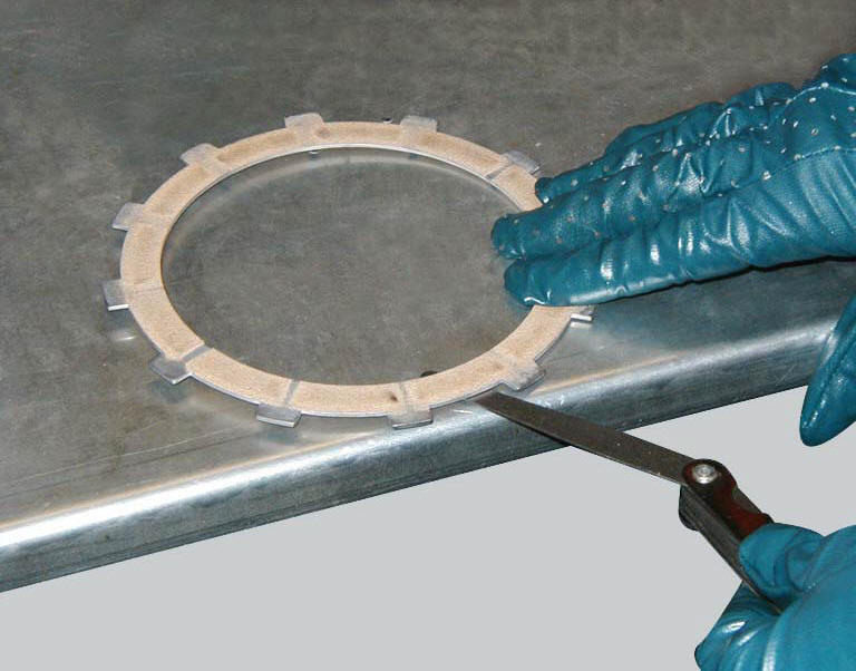
Place the plate on a flat surface and check the amount of deformation with a feeler gauge.
Max. Flatness error: 0.2 Mm.
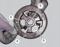
Overhaul of the pressure plate
Check bearing (5) condition; renew the bearing if the play is excessive.
Check the contact surfaces of the last friction plate; if extremely scored, polish it in the same manner as described previously for the cylinder head surface (sect. 9 - 4.5, Overhaul of cylinder head components).
Check conditions of the spring guide bucket tappet (g) of the pressure plate (4) and of the circlips (6).
Overhauling the pressure plate springs
Measure the length "l" of each spring (3).
Minimum length: 41 mm.
Renew any springs that are shorter than the above limit value.
 Removal of the clutch
Note
For clarity, the figures show the engine removed from the frame.
Undo the fixing screws (1) and remove the ring (2) and the springs (3) from
the pressure plate (4).
Slide the pre ...
 Reassembling the clutch
Position the spacer (13).
Fit the flat ring (11) and the belleville washer (10) on the clutch center
(12), so that the convex side faces the clutch
drum.
Locate the belleville washer (8). ...
Other materials:
Removal of the expansion tank
Loosen the clamp (6), open the hose guide (a) and slide the hose (7) out of
the radiator.
Open clamps (14) and release the hoses that pass through them.
Loosen the screws (16).
Remove the tank (12) with its hoses (7) and (20) and the support (15).
Loosen the clamp (19) to r ...
Removal the airbox and throttle body
Loosen the screws (a) and remove the plate (b) that fixes the main wiring to
the airbox.
Undo the screws (17) and remove the air pressure sensors (9) with the support
(19).
Release the hoses (c) of the air pressure sensors (9) from the tab (d) on the
airbox.
Operating on the ...
Reassembly of the oil pump
Check that the circlip (3) and tongue (13) are present on the pump.
Fit the pump drive gear (12) on to the oil pump and secure it by installing the
circlip (6) in its groove.
Insert the by-pass valve pump (17), the spring (16) and screw the plug (14).
Tighten the plug (14) to a torque of ...