
Ducati Diavel Service Manual: Checking and adjusting the valve clearances
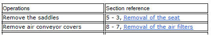
Note
For clarity, the figures show the engine removed from the frame.
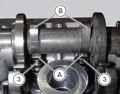
Move the piston of the cylinder being checked to tdc of the power stroke: in this condition, all the valves are closed and the timing shafts come in neutral position and, therefore, free to rotate; check to the valve clearance on the cylinder head on which it operates.
Checking the opening clearance
Using a feeler gauge, check the clearance between the opening rocker arm (a) and the lowest point of the camshaft lobe (b), taking care not to compress the rocker arm return spring.
The value must be within the specified ones (sect. 3 - 1.1, Timing system/valves).
If not, remove the opening adjuster (3), as described in paragraph "removing the valves" (sect. 9 - 4.5), And replace it with one of suitable height to obtain the prescribed clearance.
Note
Opening rocker arm shims measuring 1.80 To 3.45 Are available as replacement parts: the size is punched on the shim.
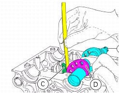
Checking the closing clearance
Using a feeler gauge, check the clearance between the closing rocker arm (c) and the highest point of the camshaft lobe (d).
The value must be within the specified ones (sect. 3 - 1.1, Timing system/valves).
If not, remove the closing adjuster (1), as described in paragraph "removing the valves" (sect. 9 - 4.5), And replace it with one of suitable height to obtain the prescribed clearance.
Note
Closing rocker arm shims measuring from 2.2 To 4.5 Are available as replacement parts: the size is punched on the shim.
 Checks and adjustments
Closing shim
Intake side camshaft
Opening shim
Exhaust side camshaft
Valve
Spare parts catalogue
Diavel abs cylinder head: timing system
Diavel abs vertical cylinder head
Diavel a ...
 Checking valve lift
Set the engine to the configuration described for the "checking and adjusting
the valve clearances", previously indicated.
Position the tool 88765.1518 On the cylinder head: the part marked "a" s ...
Other materials:
Fuel pressure test
Note
The on-screen icons used during this procedure are explained in a table at
the end of this section.
Undo the screws (2) and remove the flange cover (1).
Remove one of the two pipes of the fuel system (3).
Use the fuel pressure pipe (4) part no. 590.1.189.1A by connecting one e ...
Engine torque settings
*Dynamic safety-critical point; tightening torque must be within nm +/-5%.
Note
For product specifications and symbols, refer to paragraph "product
specifications" (sect. 1 - 2). ...
Removal of the front wheel
Support the bike so that the front wheel is raised from the ground.
Remove the front brake calliper (b) by unscrewing the two screws (a) securing
the calliper to the fork leg; do not
disconnect the calliper from the hose.
Warning
Do not operate the brake lever when the callipers are ...