Ducati Diavel Service Manual: Indicator air - air temperature
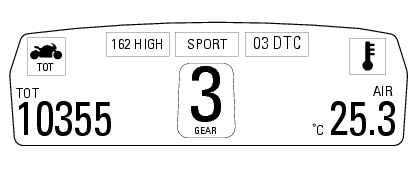
This function shows the external temperature.
Display limits: -39C - +124C
In the event of a sensor fault (-40C, +125C or disconnected), a string of dashes "- - -" (not flashing) is displayed and the "vehicle/engine diagnosis - eobd" light comes on.

Note
When the vehicle is stopped, the engine heat could influence the displayed temperature.
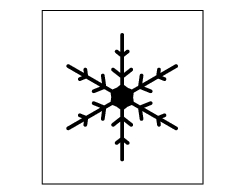
When the detected temperature drops to 4C (39f), the display warns that the formation of ice is possible. The indication turns off when the temperature rises to 6C (43f).

Warning
This warning does not exclude the possibility of icy road sections even at temperatures above 4C (39f); when external temperatures are "low" it is always recommended to ride carefully, particularly on sections that are not exposed to the sun and/or on bridges.
 Indicator trip time - trip time
This function shows the vehicle trip time.
The calculation is made considering the time travelled since the last trip 1
reset. When trip 1 is reset, the value is set to
zero.
The active phase ...
 Engaged gear indicator
This function displays the gears (1).
The dashboard receives information and indicates the engaged gear or "n" for
neutral.
In the case of a gear sensor "error", a dash "-" (not flashing) will ...
Other materials:
Checking brake and clutch fluid level
The levels should not fall below the min marks on the
respective reservoirs.
If the level is too low, air can get into the circuit, thus
impairing the efficiency of the system.
Brake and clutch fluid must be topped up and changed at the
intervals specified in the scheduled maintenance table ...
How to use this manual
How to use this manual
This manual has been prepared for technical personnel at ducati authorized
service centres with the aim of providing
fundamental information on how to work in accordance with the modern concepts of
"best practice" and "safety in the
workplace" during the maintenance, re ...
Removal of the air filters
Work on the vehicle right side, loosen screws (3) that secure the intake duct
(2) to the airbox, and the radiator retaining
screw (a); recover the washer (b).
Remove the intake duct (2).
Proceed in the same way to remove the lh intake duct (6), and disconnect the
connector (c) ...