
Ducati Diavel Service Manual: Reassembly of the control unit
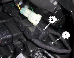
Insert the control unit (4) into the protecting sheath (5) and position it on the airbox.

Position the relay supporting bracket (2) by starting and tightening the screws (1) to a torque of 6 nm +/- 10% (sect. 3 - 3, Frame torque settings), and connect the control unit connectors (3).

 Removal of the control unit
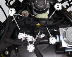
Loosen the screws (1) and remove the relay supporting bracket (2), disconnect
the connectors (3) and remove the control
unit (4) from the vehicle.
...
 Fuel system circuit
The fuel system circuit consists of:
An electric pump, driven by the injection relay, which is in turn
controlled by the ecu (engine control unit)
A fuel filter
A pressure regulator
Two i ...
Other materials:
Indicator speed avg - average speed
This function shows the average speed of the motorcycle.
The calculation is made considering the distance and time
travelled since the last trip 1 reset. When trip 1 is reset, the
value is set to zero and the first available value is shown on
the display 10 seconds after the reset. Dashes &quo ...
General maintenance indications
Useful tips
Ducati recommends that you follow the instructions below in order to prevent
problems and obtain the best end result:
When diagnosing faults, primary consideration should always be given to
what the customer reports about motorcycle
operation since this information can highli ...
Disassembly of gear interlock plunger and pawl assembly
Unscrew the interlock plunger screw (5) and remove the seal (6), spring (7)
and the detent ball (8).
Unscrew the clutch-side crankcase half screw (3) and remove the pawl (4),
washer (2) and spring (1).
...