
Ducati Diavel Service Manual: Refitting the rear wheel eccentric hub and rear wheel shaft
Refitting is the reverse of removal, with attention to the following points.
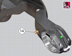
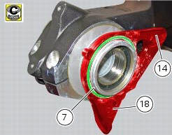
If the calliper bracket locating pin (14) was removed, apply the recommended threadlocker on reassembly.
Tighten the pin (14) to the torque of 33 nm +/- 5% (sect. 3 - 3, Frame torque settings).
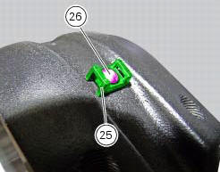
If previously removed, refit the cable grommet (25) as shown in the figure and tighten the screw (26) to a torque of 1 nm +/- 10% (sect. 3 - 3, Frame torque settings).
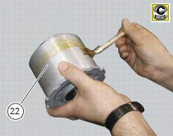
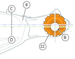
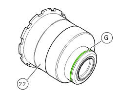
Before refitting apply some recommended grease to the eccentric hub (22) external surface.
Insert the hub (22) fully home on the swingarm (8).
Note
During this operation force the hub seat open on the swingarm enough to fit the hub (22).
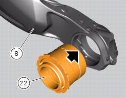
Check that the eccentric hub (22) with respect the swing arm (8) features the horizontal axis (d) of the hub bore (b) under the horizontal axis (c) of the hub seat.
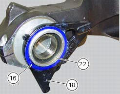
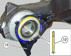
Apply grease on rings (17) and place them in their seat of the plate (18). Fit the washer (16) on the eccentric hub (22).
Place the plate (18) on the swingarm: the pin (14) must match with the blind slot (t) on the plate (18).
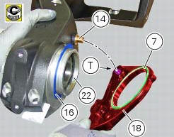
Refit the other washer (16) on the eccentric hub (22).
Block the plate (18) after installing circlip (19) in its groove (g) on hub (22), and setting it with its square edge outward.
Note
After this operation visually check that the circlip is perfectly inserted in the groove (g).
Apply an even coating of the recommended grease in the areas (a) of the axle (31).
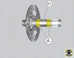
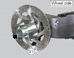
Insert the rear wheel shaft (31) in the hub (22).
Ensure the stub axle (31) is seated in the hub.
Fit the inner ring (21) on the wheel shaft (31).
Insert the inner ring (21) in the hub.
Apply the recommended grease to the screws (a) and tighten to the torque of 35 nm+/-5%(sect. 3 - 3, Frame torque settings) following the sequence 1-2-1.

Set the chain tension as described in sect. 4 - 3, "Adjusting the chain tension".
 Removal of the rear wheel eccentric hub and rear wheel shaft
Before removing the eccentric hub, you must first remove the parts listed
below.
Slacken off the screws (34).
Remove the spacer (20) and the inner ring (21) on the chain side and remove the ...
 Removal of the swingarm
Before removing the parts in question, you must first carry out the following
operations:
Remove the rear wheel eccentric hub as described in chapter "removal of the
rear wheel eccentric hub ...
Other materials:
Checking and adjusting timing belt tension
Note
The on-screen icons used during this procedure are explained in a table at
the end of this section.
Note
This operation, which is performed using the dds diagnosis instrument, has
the advantage that it can be carried out on
both timing belts with the engine still installed on the frame. ...
Operations to be carried out by the dealer
List of operations to be performed every 12000 km / year (first
limit reached)
Reading of the error memory with dds on the engine control units,
vehicle and abs
Change the engine oil
Change the engine oil filter
Check and/or adjust valve clearance ( ...
Information about the model
Identification data
Diavel identification data
Each ducati motorcycle has two identification numbers -the frame number and
the engine number- and an ec nameplate
(a) (not present on the us version).
Note
Please quote these numbers, which identify the motorcycle model, when
ordering spare pa ...