
Ducati Diavel Service Manual: Refitting the clutch transmission unit
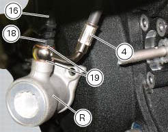
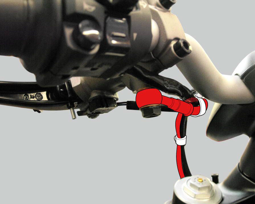
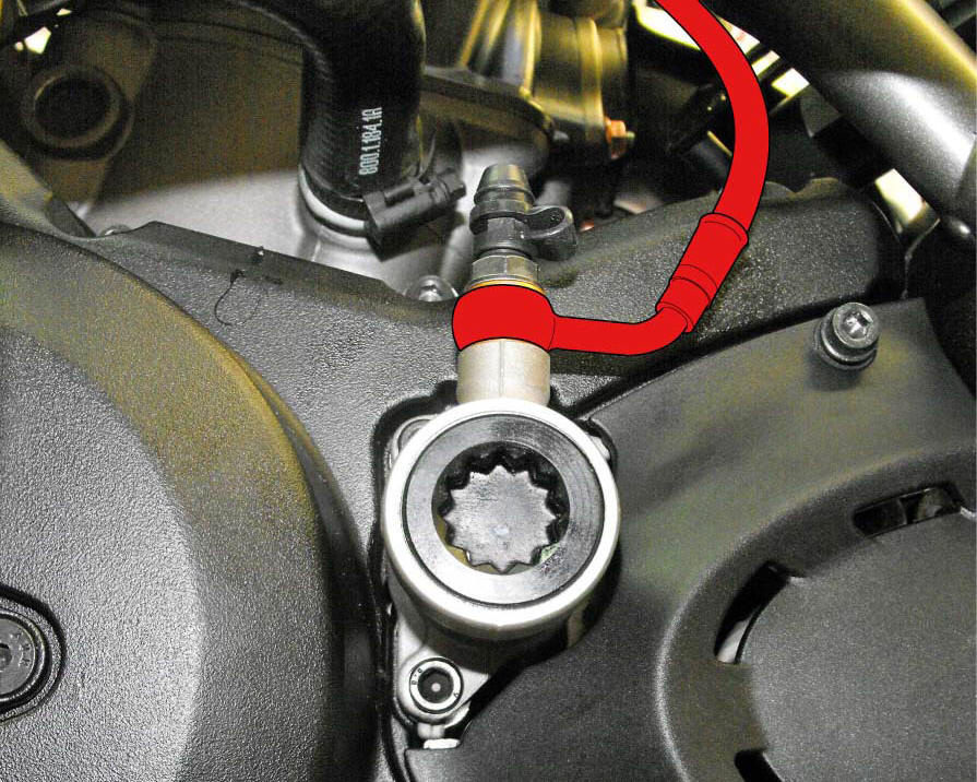
Position pipe (4) on the clutch slave cylinder (r).
Position the two seals (19) and tighten the screw (18) to a torque of 23 nm +/- 10% (sect. 3 - 3, Frame torque settings).
Refit the bleed valve (17) and the dust gaiter (16).
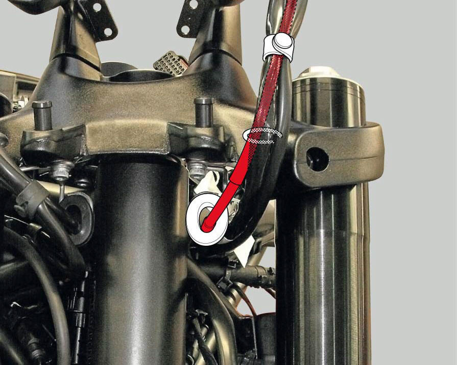
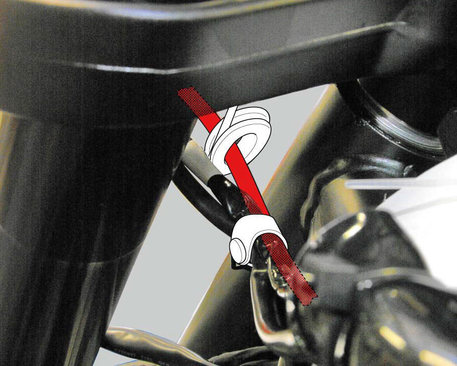
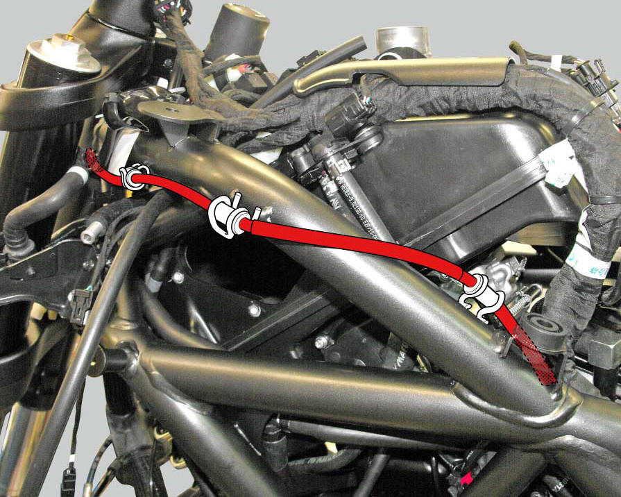
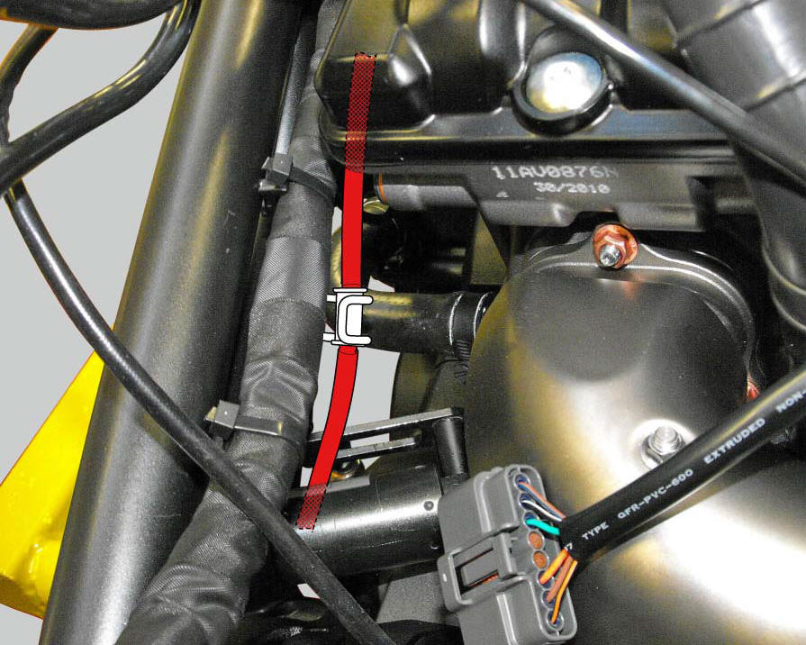
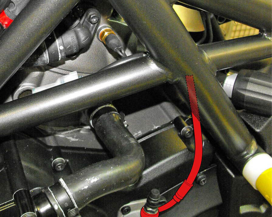
To position the pipe retaining clamps (4) refer to the table on the following page.
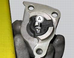
Push in the internal piston (a) to force out all the fluid from inside the cap.
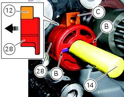
Make sure the anti-rotation pin (12) is fitted on the clutch pushrod (14).
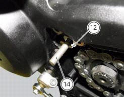
Proceed as follows in case the anti-rotation pin (12) has been removed from the clutch pushrod (14).
Turn the clutch pushrod (14) until the axis of the anti-rotation pin (12) positioning hole is horizontal, as shown in the figure; grease the anti-rotation pin (12) and insert it into the clutch pushrod (14) hole.
Insert the anti-rotation insert (28) fully home into the clutch pushrod (14) by matching the anti-rotation pin (12) with the slots (b) on the insert (28).
Note
The tab (c) of insert (28) must be inwards (casing side).
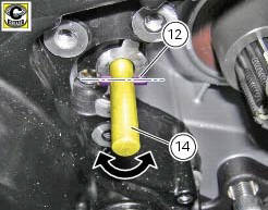
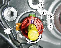
Turn the clutch pushrod (14) counter clockwise until the hole axis of the anti-rotation pin (12) is aligned with the centreline of the casing cover machined surface (d), as shown in the figure.
Insert the clutch actuator (r) into the pushrod (14) and bring it fully home on the anti-rotation insert (28).
Note
Upon insertion of the clutch actuator (r), make sure that the tab (c) of insert (28) matches with the actuator slot (e).
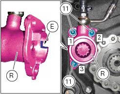
Fix the clutch actuator (r) by starting the screws (11).
Note
To bring the clutch slave cylinder (6) internal surface near the casing cover as uniformly as possible, screw and tighten the screws (11) alternatively.
Tighten the screws (11) to a torque of 10 nm +/- 10% (sect. 3 - 3, Frame torque settings), by following the sequence 1 - 2 - 3 - 1.
Positioning of the clutch hose
 Removal of the clutch transmission unit
Warning
The manufacturer of the clutch transmission unit (15) advises
against servicing of its internal parts due to the safetycritical
nature of this component.
Incorrect overhaul of these cri ...
 Hands free
Hands free
Special screw
Plug
Electric fuel plug
Button
Spring
Frame
Elastic pin
Spare parts catalogue
Diavel abs handlebar and controls
Diavel carbon
abs
handlebar and con ...
Other materials:
Refitting the water pump
Clean the seat on the cover, any parts you intend to reuse, and the impeller
shaft. Then refit as follows.
Fit on the impeller (10) shaft the mechanical seal (9) as indicated in the
figure.
Apply specified lubricant to facilitate the insertion.
Bring the mechanical seal fully home on th ...
Injectors
Introduction
The injectors used on the diavel are top feed units, meaning that fuel is fed
into the top of the injector itself. The
injectors contain a winding which raises a needle when electrically energised.
This opens the atomiser nozzle, through
which pressurised fuel is dispensed, gener ...
Removal of the cylinder/piston assembly
Loosen the clamps (7) and remove the hoses (8) and (9) from the cylinder
barrels (10) and from the alternator-side
crankcase cover.
If damaged, unscrew the unions (6).
Note
The following procedure is described with the engine removed from the
frame and the cylinder head r ...