
Ducati Diavel Service Manual: Refitting the front wheel
When all the necessary inspections have been completed, refit the wheel as follows.
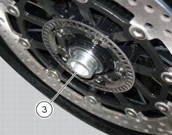
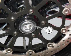
Fit the spacers (3) and (9) to the seal rings on the sides of the wheel hub.
Install the complete wheel between the fork legs.
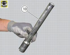
Lubricate the shank and thread of the wheel axle (10).
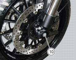
Take the pin (10) fully into the wheel hub.
Fit the washer (2) on the end of the axle.
Grease the thread and the underside of the head of the axle lock nut (1), then screw it on.
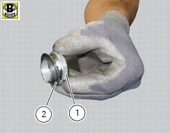
Tighten the nut (1) to the torque of 63 nm +/- 5% (sect. 3 - 3, Frame torque settings).
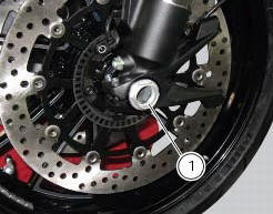
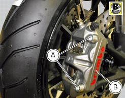
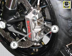
Grease the threads and undersides of the heads of screws (a).
Tighten the two retaining screws (a) of the brake callipers (b) to a torque of 2 nm +/- 10%. (Sect. 3 - 3, Frame torque settings) operate the front brake lever two or three times.
Hold the lever pulled towards the handgrip and simultaneously tighten the screws (a) to a torque of 44 nm +/- 5%(sect. 3 - 3, Frame torque settings).
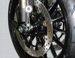
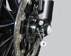
Before tightening the screws (8), lower the bike to the ground and push up and down on the handlebar to load the suspension; so the fork legs will become properly seated onto the wheel shaft.
Tighten the screws (8) to a torque of 10 nm +/- 5% (sect. 3 - 3, Frame torque settings), proceeding in a 1-2-1 sequence.
 Overhauling the front wheel
Wheel bearings
Before checking the dimensions, check the wear on wheel bearings. Check for
wear by hand after cleaning and degreasing
the bearings in their seats.
Turn the inner race.
Check ...
 Rear wheel
Right-hand wheel nut
Washer
Spacer
Valve
Wheel
Circlip
Spare parts catalogue
Diavel abs front and rear wheels
Diavel carbon
abs
front and rear wheels
Important
Bold reference ...
Other materials:
Checking the idle speed
Check that the bike is provided with electronic control unit, oem intake and
exhaust systems, otherwise fit original
components.
Connect the inserts of the exhaust gas analyser code 88713.1010 To the outlets
on the exhaust pipes, using the fittings
(1).
Warning
Make sure that the thro ...
Recovery procedure in the event of hands free system fault
If the hands free system can no longer communicate with the other control
units over the can network (with the
dashboard or engine on), the following icon is shown on the tank dashboard:
The following image shows the icon appearing on the tank dashboard: this
indicates that the hands free sy ...
The hands free relay
Introduction
This relay provides key on +15 power to all the devices on the motorcycle.
Functionally, it replaces the conventional
ignition switch.
Wiring diagram
The hands free relay receives +12 volt power directly from the battery via
the main 30 a fuse. Hands free - 3: pin 3 on
hand ...