
Ducati Diavel Owners Manual: Engine setting function (engine power control)
This function customises engine power and output.
To access the function it is necessary to view the "setting" menu page 48, using
button (1, fig. 14) ?"
"or (2, fig. 14) ?" "select the "riding mode"function
and press the
reset button (12, fig. 12) To go to next page.
Use button (1, fig. 14) ?" "or (2,
fig. 14) ?" "to select the riding
mode to be changed and press the reset button (12, fig. 12) To access the next
page. Now use button (1, fig. 14) ?"
"and (2, fig. 14) ?"
"to select the "engine" indication
and press the reset button again (12, fig. 12) To confirm
selection.
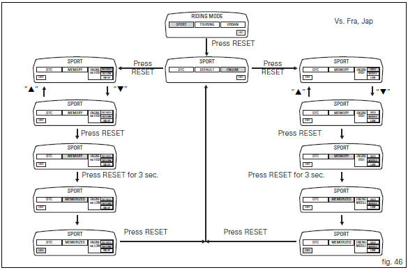
When accessing the function, the engine setting (engine 162 high, 162 low o 100 hp) appears at the right-hand side of the display, inside a rectangle.
 Note
Note
In japan and france versions, the display displays the settings (engine high, middle or low).
Using button (1, fig. 14) ?"" or
(2, fig. 14) ?" " select one of
the three available engine settings; after selecting the new
setting, press the reset button (12, fig. 12) To highlight
"memory" indication.
At this point, store the new setting by pressing and holding the reset button (12, fig. 12) For 3 seconds with "memory" displayed. If the setting has been stored successfully, the display will show "memorized" in green for 2 seconds and the exit option will be highlighted automatically.
To exit the setting function, press the reset button (12, fig.
12) Where "exit" is highlighted.
 Tips for use on the road
Activate the dtc, select level 8 and ride the motorcycle in
your usual style; if the level of dtc intervention seems
excessive, try reducing the setting to levels 7, 6, etc., Until
you find the lev ...
 Default function (resetting ducati default parameters)
This function resets the parameters set by ducati for each
riding style.
To access the function it is necessary to view the "setting" menu page 48, using
button (1, fig. 14) ?"
...
Other materials:
Abs system operating information
The response of the system is based on the analysis of the speed signals for
front and rear wheels; the system is
automatically deactivated if either of these signals is missing.
Note
In the event of the abs control unit detecting a fault in the abs
electronic management system, it activates ...
Cylinder/piston assemblies
Piston
Gudgeon pin circlip
Gudgeon pin
Set of piston rings
Cylinder-crankcase gasket
Water pump outlet union
Hose clip
Horizontal cylinder coolant inlet hose
Vertical cylinder coolant inlet hose
Cylinder barrel
Cylinder head gasket
Bush
Spare parts catalogue
Diavel a ...
Refitting the timing belts
Rotate the pulleys on the timing belt driveshaft until the timing mark on the
outer roller is aligned with the mark on the
clutch-side crankcase cover.
In this condition, the horizontal cylinder piston will be at top dead centre.
Install in the alternator cover seat the tool code 88713.20 ...