
Ducati Diavel Service Manual: Refitting the rear footrests
Note
The refitting of the rear footrests is described for the right side but it is the same for both.
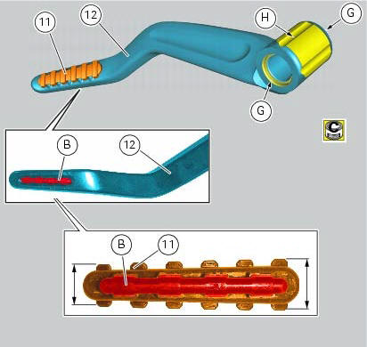
If previously removed, refit the rubber footrest (11) on the rear rh footrest (6), by pushing it until pad (b) engages in the other side.
Note
The rubber footrest (11) side featuring the least width must be faced to the outer side of the footrest (12).
Apply recommended grease to the seats (g) of the o-rings and in area (h) on the rear rh footrest (12).
Place o-rings (9) in the relevant seats of the footrest (12).
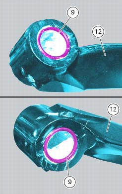
Position footrest (12) as shown, on the rear subframe rh bracket; make sure that the previously fitted o-rings do not come out of the relevant seats on the footrest (12).
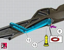
Fit washer (8) between footrest (12) and the rear subframe rh bracket.
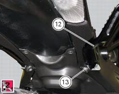
Fix the footrest (12) by starting the pin (13) smeared with specified threadlocker.
Tighten the pin (13) to a torque of 30 nm +/- 10% (sect. 3 - 3, Frame torque settings).
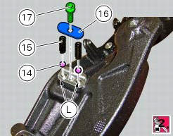
If previously removed, apply recommended grease into the holes (l) and insert balls (14) and springs (15) into the relevant holes of the rear subframe rh bracket.
Apply prescribed threadlocker on the screw thread (17).
Fit the cap (16) and tighten the screw (17) to a torque of 10 nm +/- 10% (sect. 3 - 3, Frame torque settings)
 Removing of the rear footrests
The removal of the rear footrests is described for the right side but it is
the same for both.
Undo the pin (13) and remove the rh rear footrest (12) from the frame.
Recover washer (8) and the ...
 Stands
Side stand
Side stand switch
Screw
Plate
Screw
Inner spring
Outer spring
Nut
Rotation pivot
Screw
Screw
Screw
Nut
Clearance adjuster
Spare parts catalogue
Diavel a ...
Other materials:
Riding safety
The points given below are applicable for every day
motorcycle use and shoud be carefully observed for safe and
effective vehicle operation.
A motorcycle does not provide the impact protection of an
automobile, so defensive riding in addition to wearing
protective apparel is extremely importa ...
Disassembly of the clutch cover
Remove the plug (14) and its o-ring (13), the plug (17) and its o-ring (15)
from the cover.
Undo the fixing screw (16) of the inner cover (19).
Remove the inner cover (6) and soundproofing panel (18).
Remove the circlip (10) and withdraw the shim (9) and the sealing ring (8).
The dri ...
Steering angle adjustment
Loosen the nuts (17) and adjuster screws (16) on both sides of the bottom
yoke.
Use a 6 to 6.5 Mm spacer (a) fitted to the fork outer tube, or use a gauge.
Turn the front forks to the right until the spacer (a) is seated against the
frame top tube.
Tighten the adjuster screw (16) to ...