
Ducati Diavel Service Manual: Removal of the fuel tank fairings
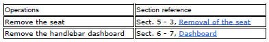
Remove the rh air inlet (7) by loosening screws (6) and (9).
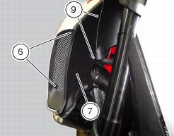
Undo the retaining screw (3) of the rh front half-fairing (1).
Slightly pull the pin (a) to disengage it from the seal (b), and remove the rh front half-fairing (1) by sliding it onwards and releasing the tabs (c) from the seals (d).
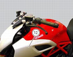
Follow the same procedure to remove the lh half-fairing (12).
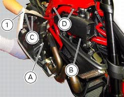
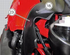
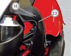
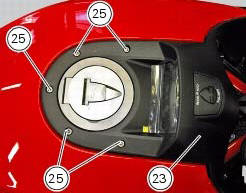
Loosen the screws (16) and (25) securing the tank plug cover (23) but do not remove it.
Lift the tank plug cover (23) up in order to reach the wiring (e) of the dashboard (f).
Disconnect the wiring (e) from the dashboard (f).
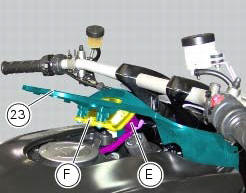
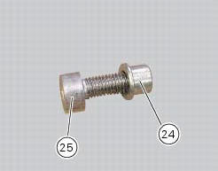
Remove the tank plug cover (23) from the vehicle recovering the screws (25) and spacers (24).
Remove the lh tank fairing (21) by loosening screws (16) and (14); recover the washers (17) and (15).
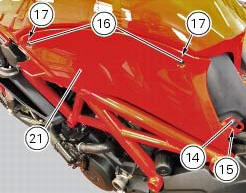
Remove the rh tank fairing (13) by loosening screws (16) and (14); recover the washers (17) and (15).
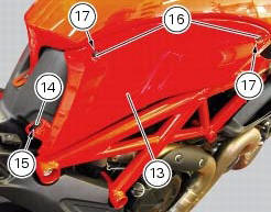
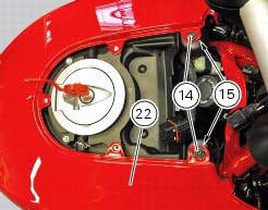
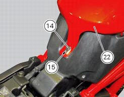
Remove the tank fairing (22) by loosening the screws (14); recover the nylon washers (15).
 Fairings
Rh front half-fairing
Clip
Screw
Right-hand support
Screw
Screw
Rh air inlet
Lh air inlet
Screw
Clip
Left-hand support
Lh front half-fairing
Lh tank fairing
Screw
Ny ...
 Disassembly of the front half-fairings
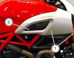
Undo the screws (5) and separate the rh support (4) from the front right
half-fairing (1).
Follow the same procedure to disassemble the lh half-fairing (12). ...
Other materials:
Refitting the steering head components
Important
The steering tube bearings (6) are identical but in no case may their
components be swapped around during reassembly.
Clean all contact surfaces and lubricate with the recommended grease.
To fit the external rings (c) of the bearings (6) to the steering tube, use the
tool with par ...
Low beam lights not working
Location of connections and components
(A) injection relay; (b) etv relay (throttle valve operating engine); (c)
radiator fan relay; (d) hands free relay.
Fuses located at the rear left of the vehicle.
(1) 10A dashboard; (2) 5a engine control unit; (3) 15a key-sense; (4) 20a
injecti ...
Removal of the licence plate holder
Disconnect connector (5) of the number plate holder wiring from the main one.
Release the number plate holder light cable from the ties and the cable grommets
as indicated in sect- 7 - 6, flexible
wiring/hoses positioning, since the cable is together with the rear abs sensor
cable.
...