
Ducati Diavel Service Manual: Removal of the lubrication system
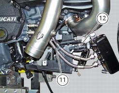
Disconnect the sensor (12) of the main wiring.
Open the pipe grommet (11).
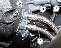
Undo the screw (8) and slide out the plate (9).
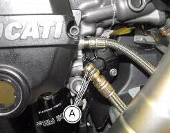
Slide the tubes (7) out of the half-casing having care not to damage the tubes o-rings (a) that guarantee the coupling sealing.
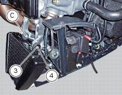
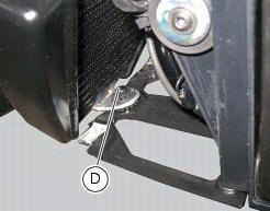
Undo and remove the screw (4) with the spacer (3). Remove the radiator by sliding it out of pins (c) and (d).
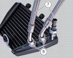
Loosen the nuts (g) of the pipes (7) from the nipples (5) and disconnect it from the radiator.
Loosen the nipples (5) on the radiator and collect the gaskets (6).
Oil cooler inspection
Visually inspect the oil cooler. Renew the cooler at any sign of damage or leaks.
 Oil cooler
Oil cooler
Vibration damper mount
Spacer
Screw
Nipple
Aluminium gasket
Oil delivery hose
Screw
Plate
Bracket
Screw
Engine oil pressure sensor
Sealing washer
Heat guard ...
 Refitting the lubrication system
Note
Before fitting the pipes (7), it is recommended to check the presence of
the o-rings (e). Lubricate them by using engine
oil.
If the nipples (5) have been removed from the radiator inser ...
Other materials:
Checking valve clearances
To check the valves clearance, it is necessary to have access to the cylinder
head covers and then remove the
components listed below.
Unscrew the two fixing screws (1) of the cover (2) according to the
crankshaft.
Fit the tool handgrip 88713.0123 In the holes of the generator cover t ...
Description of the clutch assembly
The clutch is disengaged by a drive unit consisting of a thrust piston (c)
accommodated inside a small cap mounted to
the generator cover. This piston (c) pushes a pushrod (b), which runs through
gearbox primary shaft and operates the Pressure plate (4)
located on top of the clutch plate pack ...
Tft - parameter setting/display
Warning
Any adjustments to the instrument panel must only be
carried out when the motorcycle is stationary. Never operate
the instrument panel controls while riding the motorcycle.
At the end of the check, the instrument panel always
displays as the "main" indication the odometer (to ...