
Ducati Diavel Service Manual: Removal of the rear brake disc
Remove the rear eccentric hub (sec. 7 - 13, Removal of the rear wheel eccentric hub and rear wheel shaft).
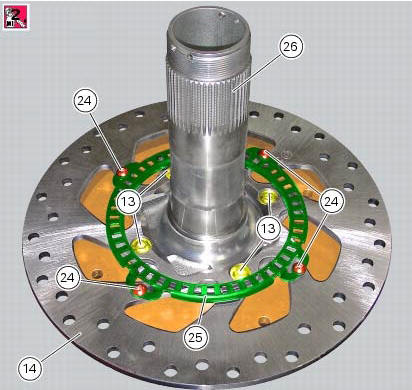
Undo and remove the four fixing screws (13) of the brake disk to the wheel axle and remove the rear brake disk (14).
Loosen the four screws (24) and remove the rear phonic wheel (25).
The brake disc must be perfectly clean, with no rust, oil, grease or other dirt and no deep scoring.
To check the wear limit of the brake disk refer to sec. 3 - 1.1, Hydraulic brakes.
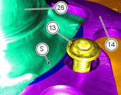
Place the rear brake disc (14) on the rear wheel shaft (26), by orienting the bevelled edges (s) faced upwards.
Fix the disc by starting the screws (13) with prescribed threadlocker.
Note
Make sure to centre the screw heads in the relevant seats on the brake discs.
Tighten the screws (13) to a torque of 27 nm +/- 10% (sect. 3 - 3, Frame torque settings), in the sequence 1-2-3-4.
Position the phonic wheel (25) on the brake disc (14) by orienting it as shown in figure.
Fix the phonic wheel (25) by starting the screws (24) with the recommended threadlocker.
Tighten the screws (24) to a torque of 5 nm +/- 10% in a crossed-pattern sequence.
Refit the rear eccentric hub as described in sec. 7 - 13, Removal of the rear wheel eccentric hub and rear wheel shaft.
 Removal of the rear brake calliper
Important
The brake manufacturer advises against any servicing of the internal
components of brake callipers or the master cylinder.
Incorrect overhaul of these critical safety components can en ...
 Refitting the rear brake calliper
When replacing the brake pipes (33) or removing one of the rear braking
system components, pay special attention to the
position of the couplings on the pump and the calliper.
Warning
If incorrec ...
Other materials:
Reassembly of the gearbox
To refit the gearbox components follow the procedure under sect. 9 - 9.2,
Reassembly of the crankcase halves, relating to
reassembly of the engine crankcase.
As a final practical test, ensure that with the gearbox in neutral the front
coupling dogs (a) of sliding gears (b) are
equidistant o ...
Coolant temperature
This function indicates coolant indication state.
The temperature unit of measure can be selected (C or f).
The reading is indicated as follows:
If the reading is between - 39C and +39C "lo" is
shown flashing on the instrument panel (steady);
If the reading is between +40C an ...
Overhaul of the gearbox
Check the condition of the front coupling dogs of the gears. They must be in
perfect condition and with no sign of wear on
the edges of the teeth.
The idler gears must rotate freely on their shafts.
When refitting, make sure the circlips are correctly positioned.
Check the needle roller ...