
Ducati Diavel Service Manual: Removal of the rear brake calliper
Important
The brake manufacturer advises against any servicing of the internal components of brake callipers or the master cylinder.
Incorrect overhaul of these critical safety components can endanger rider and passenger safety.
Before removing the parts in question, you must first carry out the following operations:
note
For the abs front braking system, also refer to sect. 7 - 5, Abs system operating information, sect. 7 - 6, System components, sect. 7 - 7, Abs components maintenance.
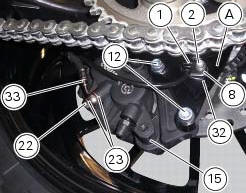
Unscrew and remove the special screw (22) fixing the pipes (33) to the rear brake calliper and the corresponding couplings (23).
Remove tube (33).
Undo the two fixing screws (12) of the rear brake calliper (15) to the calliper holder bracket and remove the brake calliper (15).
If it is necessary to remove the calliper holder bracket (a) refer to sec. 7 - 13, Removal of the rear wheel eccentric hub and rear wheel shaft.
Note
To replace the brake pads follow instructions in the paragraph "checking brake pad wear and changing brake pads" (sec. 4 - 3).
To remove the speed sensor (1), undo the retaining screw (2), having care not to damage the airgap spacer (8) and the washer (32).
Only the following parts should be renewed:
- Brake calliper: pads, fasteners and bleed valve assembly;
- Master cylinder: control pedal, bleed valve assembly, reservoir and its components.
Refer to the exploded view at the beginning of this section for indications on renewal of the above components.
 Refitting the rear brake control
If the pushrod (18), clip (30) and fork (31) assembly has been dismantled,
reassemble it by screwing the nut (29) onto
the rod (18) and then screw the rod into the fork (31) to obtain the measureme ...
 Removal of the rear brake disc
Remove the rear eccentric hub (sec. 7 - 13, Removal of the rear wheel
eccentric hub and rear wheel shaft).
Undo and remove the four fixing screws (13) of the brake disk to the wheel axle
and re ...
Other materials:
Lcd unit functions
Speedometer.
Gives road speed.
Rev counter.
Indicates engine revs per minute.
Clock.
Water temperature indicator.
Indicates engine coolant temperature.
Important
Stop riding if the temperature reaches the maximum
value, otherwise the engine might be damaged.
...
Refitting the rear-view mirrors
Start the screws (2) in their thread on the rear-view mirrors (1), inserting
the washers (4) as shown in the picture.
Insert the rear-view mirrors (1) in the u-bolts (3).
Tighten the screws (2) to a torque of 25 nm +/-10% (sect. 3 - 3, Frame torque
settings).
Warning
The left rear-view ...
Adjusting the front fork
The front fork used on this motorcycle has rebound, compression and spring
preload adjustment.
This adjustment is done using the outer adjusters:
Rebound damping;
Inner spring preload;
Compression damping.
Park the motorcycle in a stable position on its side stand.
Turn the adjust ...