
Ducati Diavel Service Manual: Front brake control
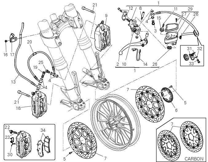
- Front brake master cylinder
- Brake lever
- Special screw
- Sealing washer
- Screw
- Phonic wheel
- Brake disc
- Pin
- Left brake calliper
- Boot
- Bleed valve
- Spare stand
- Control unit - front callipers pipe
- Microswitch
- Oil duct union
- Screw
- Hose clip
- Right brake calliper
- Special screw
- Front brake hose
- Screw
- Dust cap
- Bleed valve
- Front pump - control unit pipe
- Special screw
- Union
- Plug
- Inspection plug (replacement part)
- Fluid reservoir assembly
- Clip
- Hose clip
- Washer
- Screw
- Pair of brake pads
Spare parts catalogue
Diavel abs front brake
Diavel abs front and rear wheels
Diavel carbon abs front brake
Diavel carbon abs front and rear wheels
Important
Bold reference numbers in this section identify parts not shown in the figures alongside the text, but which can be found in the exploded view diagram.
- Removal of the front brake master cylinder
- Refitting the front brake master cylinder
- Maintenance operations
- Removal of the front brake system
- Removal of the brake discs
- Overhauling the front brake components
- Refitting the brake disks
- Refitting the front brake system
 Refitting the rear wheel
Lubricate the wheel shaft threaded end with prescribed grease.
Insert the wheel shaft by matching (a) with pins (b).
Install spacer (3) with the conical surface faced to the wheel conical ...
 Removal of the front brake master cylinder
Warning
The brake master cylinder manufacturer advises against servicing the
brake master cylinder due to the safety critical
nature of this component. Incorrect overhaul of these critical safety ...
Other materials:
Reassembly of structural components and the frame
Check for the nuts with clips (8).
Apply recommended grease on the threads of the adjusters (4) and the ring
nuts (5) having care not to have grease on
the surface (c) of the adjusters.
Tighten the adjusters on the ring nut side opposite to that featuring flats
until bringing the surfac ...
Overhauling the front forks
Note
It is advisable to loosen the top cap (14) when the fork is still fitted
to the motorcycle.
Note
The specific tools for the revision of the fork, are described in sect. 3
- 4, Specific tools for the frame.
Loosen the spring preload adjuster before unscrewing the plug (14).
Unscrew th ...
Background setting function for the instrument panel on tank - dashboard 1
This function allows setting the "background" of the
instrument panel on tank.
To access the function it is necessary to view the "setting" menu page 48, using
button (1, fig. 14) ?"
" or (2, fig. 14) ?" " select the "back light" function
a ...