
Ducati Diavel Service Manual: Checking and overhauling the components
Clearance between the clutch drum and friction plates
Insert a friction plate (e) in the clutch drum (f) and measure the clearance (s) with a feeler gauge.
Clearance "s" must not exceed 0.6 Mm.
If it does, renew the plates and, if necessary, the clutch drum.
Overhaul of the clutch plates
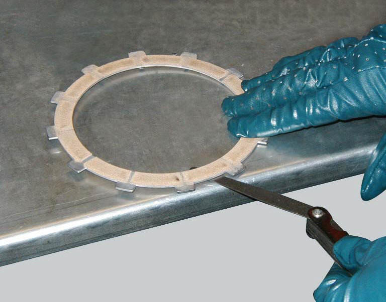
The clutch plates must not show any signs of blackening, grooves or deformation.
Measure the thickness of the friction plates; it should not be less than 2.6 Mm.
Important
The total thickness of the discs pack must not be less than 46.1 Mm.
Place the plate on a flat surface and check the amount of deformation with a feeler gauge.
Max. Flatness error: 0.2 Mm.
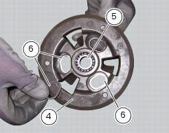
Overhaul of the pressure plate
Check bearing (5) condition; renew the bearing if the play is excessive.
Check the contact surfaces of the last friction plate; if extremely scored, polish it in the same manner as described previously for the cylinder head surface (sect. 9 - 4.5, Overhaul of cylinder head components).
Check conditions of the spring guide bucket tappet (g) of the pressure plate (4) and of the circlips (6).
Overhauling the pressure plate springs
Measure the length "l" of each spring (3).
Minimum length: 41 mm.
Renew any springs that are shorter than the above limit value.
 Removal of the clutch
Note
For clarity, the figures show the engine removed from the frame.
Undo the fixing screws (1) and remove the ring (2) and the springs (3) from
the pressure plate (4).
Slide the pre ...
 Reassembling the clutch
Position the spacer (13).
Fit the flat ring (11) and the belleville washer (10) on the clutch center
(12), so that the convex side faces the clutch
drum.
Locate the belleville washer (8). ...
Other materials:
Crankshaft/connecting rods assembly
Special screw
Connecting rod assembly
Half bearing
Grub screw
Bushes
Crankshaft
Grub screw
Shim washer
Spare parts catalogue
Diavel abs connecting rods
Diavel carbon
abs
connecting rods
Important
Bold reference numbers in this section identify parts not shown in the
f ...
Removing the frame and the lateral footrests
Loosen the two special screws (6) to separate the frame (1) from the lateral
brackets (2) and (3).
On the left side of the vehicle block retaining pins (9) and loosen the nuts (8)
on the right side at the same time.
Slide out the retaining pins (9) and remove the frame (1) from the lateral ...
Disassembly of the clutch cover
Remove the plug (14) and its o-ring (13), the plug (17) and its o-ring (15)
from the cover.
Undo the fixing screw (16) of the inner cover (19).
Remove the inner cover (6) and soundproofing panel (18).
Remove the circlip (10) and withdraw the shim (9) and the sealing ring (8).
The dri ...