
Ducati Diavel Service Manual: Component assembling position
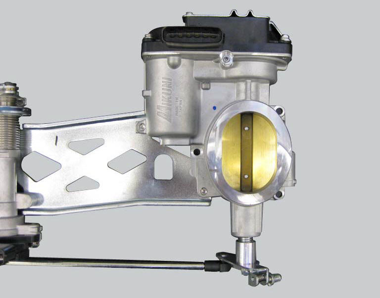
The throttle valve position sensor is integrated in the throttle valve actuator motor.
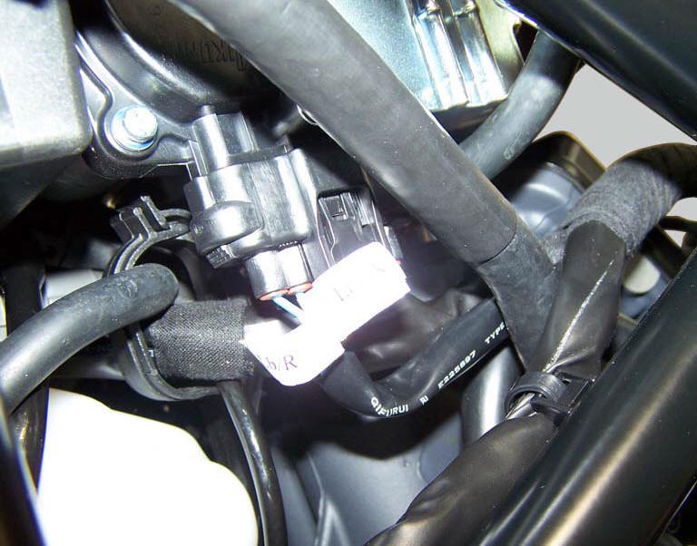
Location of electric connection for throttle valve actuator motor - tps (throttle valve position sensor).
Connection wiring diagram
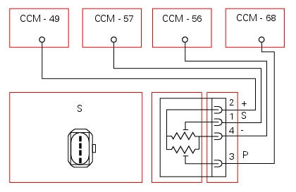
Ccm engine control connection, s throttle valve position sensor. Main potentiometer p: 3 signal, orange/blue - o/b, secondary potentiometer s: 1 signal, orange/green - o/g, 4 common ground, black/yellow bk/y, 2 common power (5v), brown/yellow - bn/y.
In the event of fault
In the event of a throttle valve position sensor fault, the ecu disables the ride-by-wire system and the engine will not start, remains running at idle or stops.
Fault codes generated and possible correlated faults
Fault codes generated by the engine control unit and displayed by the dds (throttle position sensor diagnosis):
- Short circuit to vdc: check integrity of electric circuit and electrical connections.
- Short circuit to ground: check integrity of electric circuit and electrical connections.
- Open circuit: check integrity of electric circuit and electrical connections.
- Incorrect electrical characteristics: check integrity of electric circuit and electrical connections. If the above measures do not resolve the fault, contact ducati
- Drop in power supply voltage: check integrity of electric circuit and electrical connections. If the above measures do not resolve the fault, contact ducati.
Note
Check integrity of electric circuit - short-circuit to vdc = with dashboard on, using a voltmeter, a voltage is measured between the wire tested and ground.
Check integrity of electric circuit - short-circuit to ground = with the battery cables disconnected, using an ohmmeter, continuity is detected between the wire tested and ground.
Check integrity of electric circuit - open circuit = with the battery cables disconnected, using an ohmmeter, no continuity is detected between the two ends of the wire tested.
The dashboard service display shows the error "throttle position" and the eobd warning light activates.
Possible correlated faults: the engine does not start, cuts out or remains running at idle speed and will not accelerate.
Check:
- The operation of the throttle activation motor relay (see "throttle valve actuator motor relay" of this section);
- The operation of the throttle activation motor (see paragraph "throttle valve operation engine" of this section);
The throttle valve actuator motor may be actuated into three preset positions (0%, 50%, 100%) using the dds.
The dds may be used to read the throttle valve position value.
If none of the tests described above identify the problem and the throttle valve position sensor is in proper working order, contact ducati.
Component replacement methods
The throttle valve position sensor is integrated into the throttle valve actuator motor and cannot be replaced as an individual component. In case it brakes down it will be necessary to fit a new throttle body (refer to this section operating principle and characteristics of the ride-by-wire system). After replacement of the throttle body, reset the self-adaptive parameters relative to carburation with the dds. Adjust the cables connecting the throttle grip to the throttle grip position sensor.
 Throttle valve position sensor
Introduction
The throttle valve position sensor (tps) of the diavel is mounted on the
throttle body.
The sensor is integrated into the throttle valve actuator motor, which
turns the spindle ...
 Air temperature sensor
Introduction
The engine control system on the diavel uses a sensor that measures air
temperature. This sensor has a resistance of
ntc type (negative temperature coefficient), that reduces its own ...
Other materials:
Replacing of the rear sprocket
Lock the wheel axle rotation.
Remove the clip (1).
Loosen the locking nut (2) with a socket wrench.
Fully unscrew the nut (2) and remove the washer (3) and the flange (5) with the
sprocket (17).
Collect the spacer (9).
Using a mallet, tap the flange (5) with the cush drive dampe ...
Reassembly of the gearbox shafts
Figure 1 shows all the parts to be reassembled on the gearbox primary shaft
(2), with the calculated end shims (1) and
(11) (sec. 9 - 9.2, Reassembly of the crankcase halves).
Figure 2 shows all the parts to be installed on the gearbox secondary shaft
(25), with calculated end shims (15) a ...
Clutch lever
Lever (1) disengages the clutch. It features a dial adjuster (2)
for lever distance from the twistgrip on handlebar.
The lever distance can be adjusted through 10 clicks of the
dial (2). Turn clockwise to increase lever distance from the
twistgrip. Turn the adjuster counter clockwise to decrea ...