
Ducati Diavel Service Manual: Reassembly of the gearbox shafts
Figure 1 shows all the parts to be reassembled on the gearbox primary shaft (2), with the calculated end shims (1) and (11) (sec. 9 - 9.2, Reassembly of the crankcase halves).
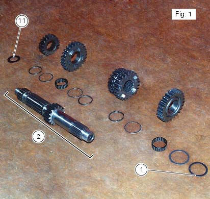
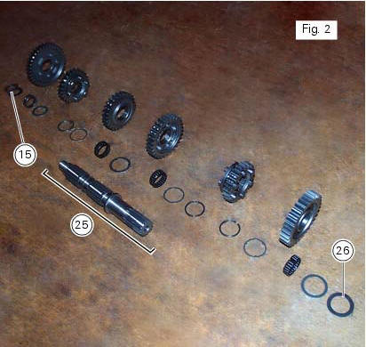
Figure 2 shows all the parts to be installed on the gearbox secondary shaft (25), with calculated end shims (15) and (26) (sec. 9 - 9.2, Reassembly of the crankcase halves).
Reassemble the gears on the gearbox shafts by reversing the disassembly procedure.
Take particular care when installing the idler gears. The assembly of the 3rd and 4th speed gears and the relative fixing components on the secondary shaft is given as an example.
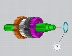
Fit the circlip (7), checking that it is fully inserted into its groove on the shaft. Push the circlip into position with a suitable size tubular drift.
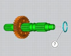
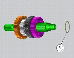
Slide the washer with three internal points (6) over the shaft until it locates against the circlip you have just fitted.
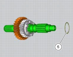
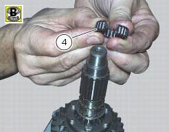
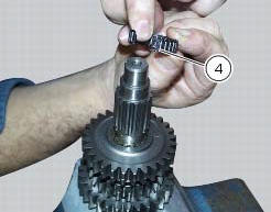
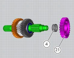
To fit the needle roller cage (4) onto the shaft, first lubricate it with plenty of grease (of recommended type) and then open it slightly to make it easier to slide on to the shaft.
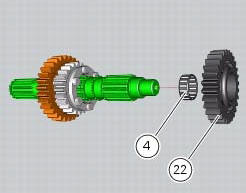
Fit the 3rd speed gear (22).
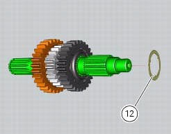
Fit on the gear the three-pointed washer (12), which can be distinguished from its counterpart (6) by its bigger outside diameter.
Fit another needle roller cage (4) using the method already described.
Fit the 4th speed gear (21).
Fit another safety washer (6) and another circlip (7) into the shaft. Push it inside its seat using the previously used pad.
 Inspection of the gear selector drum
Use a gauge to measure the clearance between fork pin and the slot on the
selector drum.
If the service limit is exceeded, determine which part must be replaced by
comparing these dimensions wi ...
 Reassembly of the gearbox
To refit the gearbox components follow the procedure under sect. 9 - 9.2,
Reassembly of the crankcase halves, relating to
reassembly of the engine crankcase.
As a final practical test, ensure th ...
Other materials:
Cylinder compression test
Note
The on-screen icons used during this procedure are explained in a table at
the end of this section.
Engine performance is directly correlated to the pressure that can be
measured in the combustion chambers of the two
cylinders. Pressure which is too high/low or an excessive difference be ...
Refitting the front brake system
While refitting the system, pay special attention to the orientation of the
pipe couplings (24) on the pump and the pipes
(13) and (20) on the callipers (9) and (18).
Warning
If incorrectly positioned, the hose can affect brake operation and
foul moving parts. Position the hose as shown in th ...
Flywheel - alternator
Screw
Alternator stator
Plug
Sealing ring
O-ring
Cover
Screw
Aluminium gasket
Screw
Bracket
Locating bush
Screw
generator cover
Flange
Flanged nut
Plane washer
Flywheel
Washer
Inner ring
Needle roller bearing
Electric starter driven gear
Starter clutc ...