
Ducati Diavel Service Manual: Refitting the camshafts
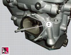
If the stud bolts (2) were removed, apply the recommended threadlocker to the short end of the stud bolts (2), i.E. The end that is to be screwed into the cylinder head. Tighten the stud bolts (2) to a torque of 10 nm (min. 9 Nm - max. 11 Nm) (sect. 3 - 3, Engine torque settings).
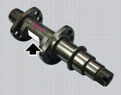
Check that the camshafts (marked "va" and "vs" for the vertical cylinder head and "os" and "oa" for the horizontal cylinder head) are clean and in good condition. If the camshafts are not new, use emery cloth to remove signs of wear on the cam and support surfaces, working on a flat surface.
Lubricate
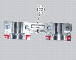
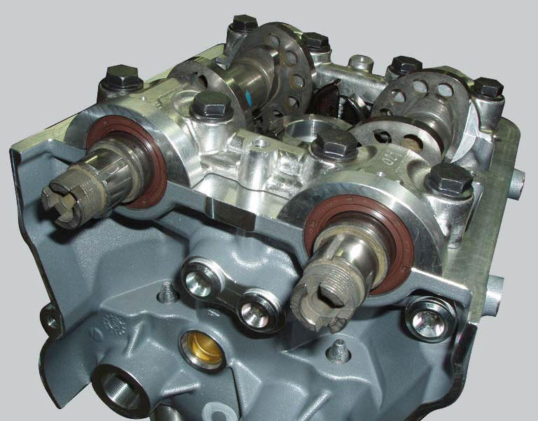
Lubricate with the specified lubricant (molykote m55 plus), the camshaft seats on both the cylinder head and the supports (22) and (23) (green zone). Fill the reservoirs (a) with the recommended lubricant (molykote m55 plus).
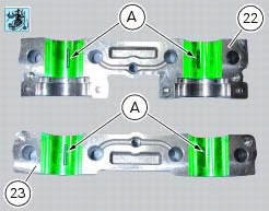
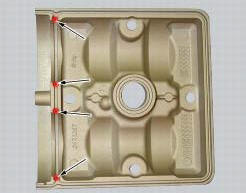
Apply sealant (three bond 1215 liquid gasket) at the four points of the support (22) shown in red in the photo. Clean off any excess sealant.
Note
Only apply sealant to the timing side support (22): do not apply to support (23).
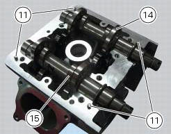
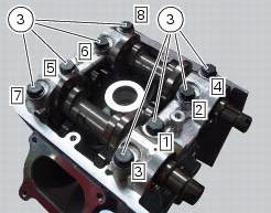
Install the camshafts (14) and (15) in the cylinder head, and rotate them to distribute the lubricant evenly.
Check that the locating dowels (11) are present.
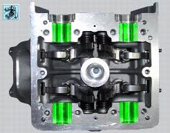
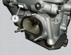
Fit the supports (22) and (23) so they are perfectly seated on the cylinder head, checking that the number stamped in zone (b) of the cylinder head is the same as the number stamped in zone (c) of the support.
Important
The support (22) must be installed on the timing side.
Bed down the supports.
Apply engine oil to the threads and undersides of the heads of the screws (3).
Insert the screws (3).
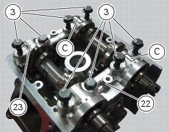
Pre-tighten the screws (3) to a torque of 10 nm (min. 9 Nm - max. 11 Nm) (sect. 3 - 3, Engine torque settings).
Pre-tighten one support at a time, working in the sequence 1-2-3-4-5-6-7-8.
Then tighten the screws to a torque of 22.5 Nm (min. 21 Nm - max. 25 Nm) (sect. 3 - 3, Engine torque settings).
Tighten one support at a time, working in the sequence 1-2-3-4-5-6-7-8.
Remove any excess sealant from between the cylinder head and the support.
Turn the camshafts by hand to check that they rotate freely.
Note
The screw (3) in position 1 must always be installed on the intake and timing side.
Important
Check lifted valve as explained (sect. 9 - 4.1, Checking valve lift).
Sealing rings
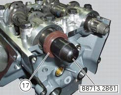
Lubricate the sealing rings (17) with denatured alcohol.
Fit the installation tool code 88713.2861 On the camshaft and install the sealing ring on the cylinder head with the spring side.
Important
Always fit new sealing rings on reassembly.
Use the drift provided with the tool and a mallet to seat the sealing rings.
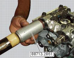
When correctly installed, the sealing ring should be flush with the bevel of the cylinder head bore.
Cylinder head cover
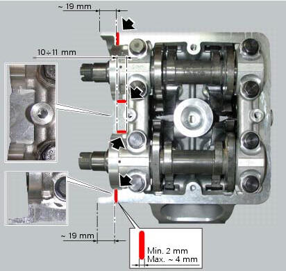
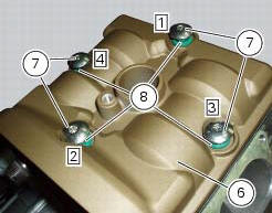
Apply sealant (three bond 1215 liquid gasket) at the four points of the cylinder head cover shown in red in the photo.
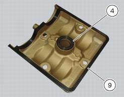
Fit the gaskets (4) and (9) on the cylinder head cover, as shown in the figure.
Apply in the four areas of the cylinder heads surface a strip of about 2 mm (max. About 4 mm) of sealant (liquid sealant three bond 1215), observing the heights and position indicated in figure.
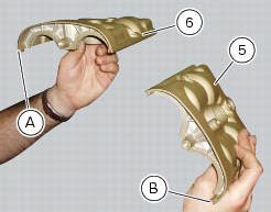
Cylinder head cover identification: the vertical head rocker cover (6) has a nib (a) on the left-hand side (exhaust side), whereas rocker cover (5) has a nib (b) on the right-hand side (exhaust side).
Locate the cover (6) on the cylinder head, aligning the four fixing holes.
Start the screws (7) with the o-rings (8).
Tighten the screws (7) to a torque of 10 nm (min. 9 Nm - max. 11 Nm) (sect. 3 - 3, Engine torque settings) following the sequence above.
Remove excess sealant from the area of application.
Repeat the same procedure for the other cylinder head.
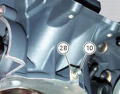
If the screw (10) has been removed, upon reassembly apply specified threadlocker, insert the seal (28) and tighten the screw (10) to a torque of 10 nm (min. 9 Nm - max. 11 Nm) (sect. 3 - 3, Engine torque settings).
Refit all the components removed in the procedure.
 Checking the camshafts and supports
Check the cam contact surfaces for scratches, grooves, steps and waving.
Worn cams are frequently the cause of poor timing, which leads to loss of engine
power.
Place the camshaft between two ...
 Removal of the intake manifold and coolant union
Loosen the clips (f) and remove the hoses (t).
Remove the manifolds (25) undoing the screws (21).
Loosen the clamp (a) and remove the hose (b). Remove the union (12) and
recove ...
Other materials:
Stored lap erase function
This function erases the stored laps.
To access the function it is necessary to view the "setting" menu page 48, using
button (1, fig. 14) ?"" or (2, fig.
14) ?"" select the "lap" function and
press the reset button
(12, fig. 12) To go to next page.
...
Removal of the brake discs
The front brake discs consist of an inner carrier, which is mounted to the
wheel, and an outer rotor. Both parts must be
changed together as a pair.
Remove the front wheel (sect. 7 - 1, Removal of the front wheel).
Undo the retaining screws (5) of the disc to the wheel, remove the disc (7) ...
Crankshaft/connecting rods assembly
Special screw
Connecting rod assembly
Half bearing
Grub screw
Bushes
Crankshaft
Grub screw
Shim washer
Spare parts catalogue
Diavel abs connecting rods
Diavel carbon
abs
connecting rods
Important
Bold reference numbers in this section identify parts not shown in the
f ...