
Ducati Diavel Service Manual: Refitting the clutch transmission unit
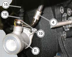
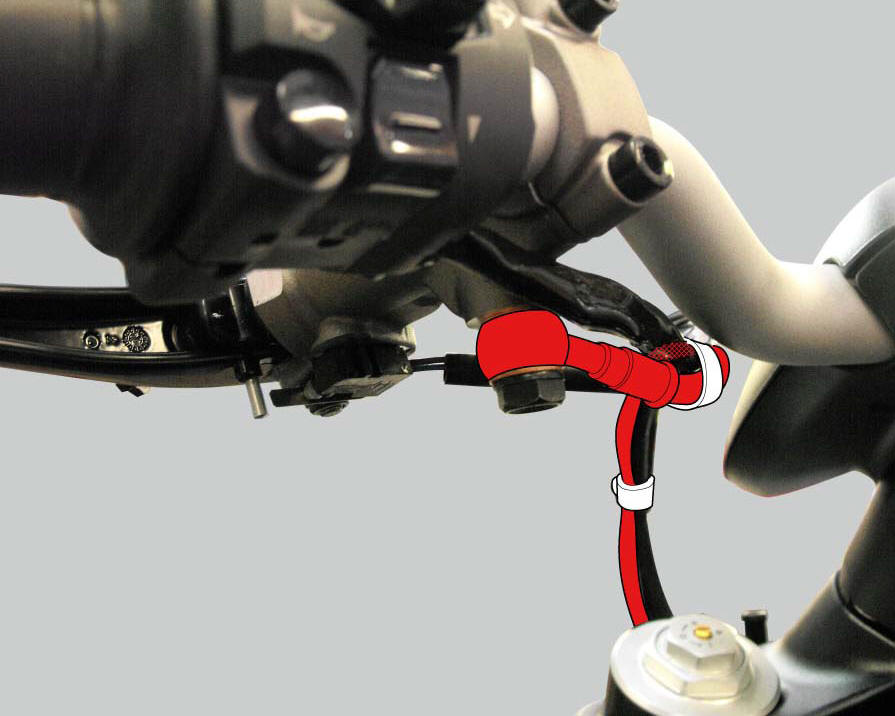
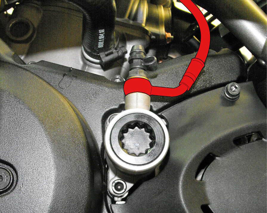
Position pipe (4) on the clutch slave cylinder (r).
Position the two seals (19) and tighten the screw (18) to a torque of 23 nm +/- 10% (sect. 3 - 3, Frame torque settings).
Refit the bleed valve (17) and the dust gaiter (16).
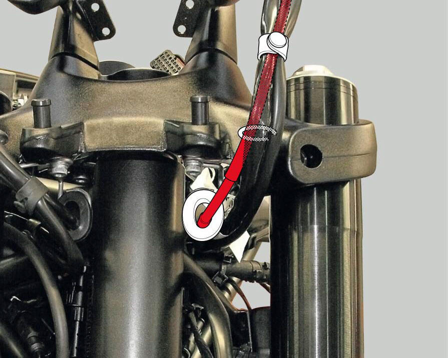
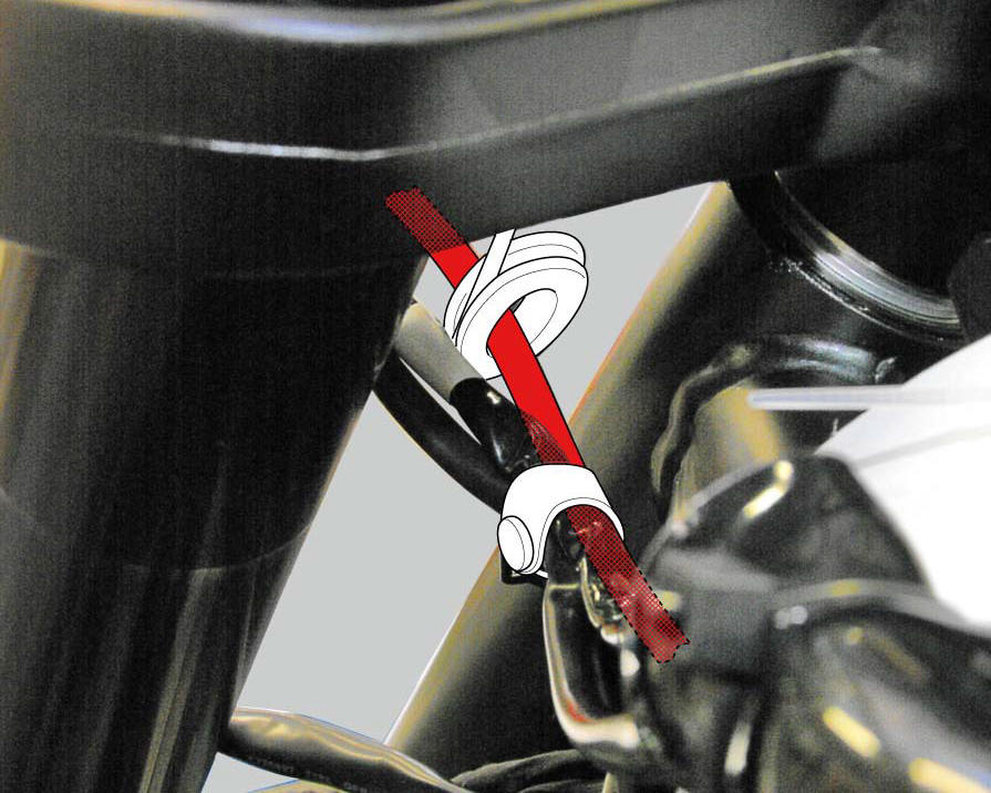
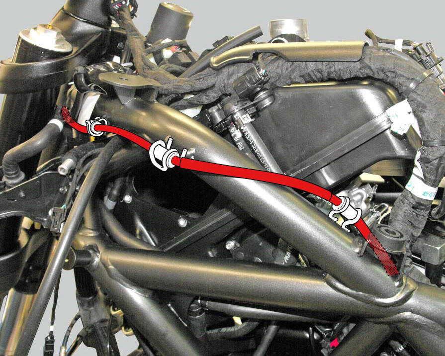
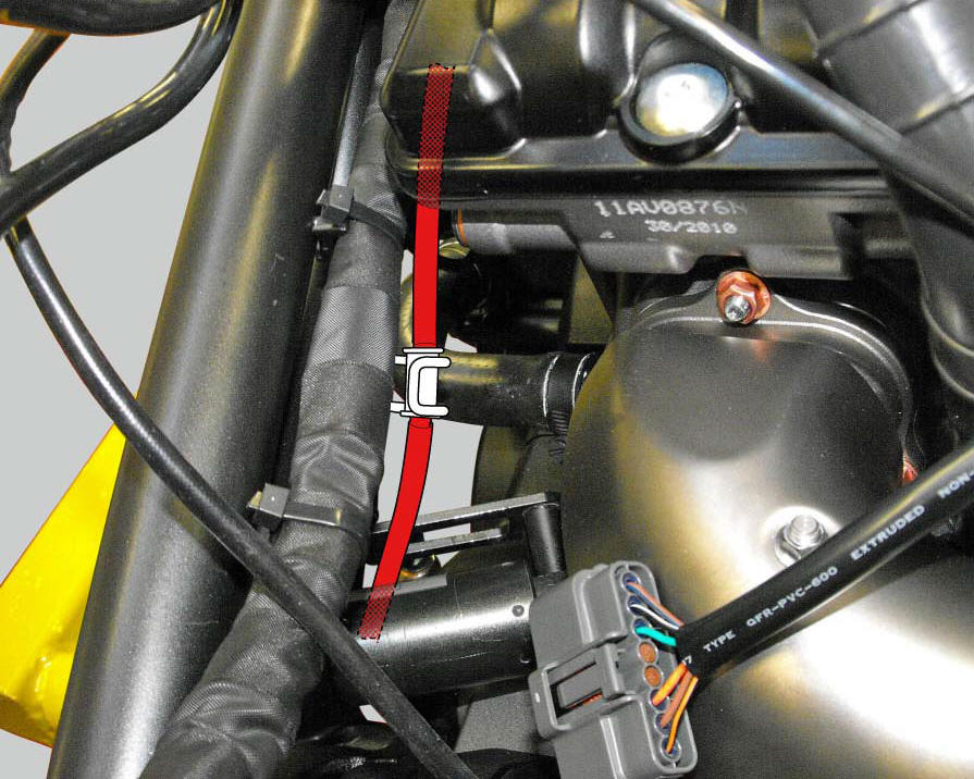
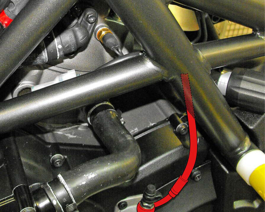
To position the pipe retaining clamps (4) refer to the table on the following page.
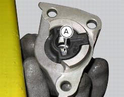
Push in the internal piston (a) to force out all the fluid from inside the cap.
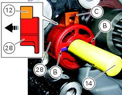
Make sure the anti-rotation pin (12) is fitted on the clutch pushrod (14).
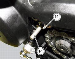
Proceed as follows in case the anti-rotation pin (12) has been removed from the clutch pushrod (14).
Turn the clutch pushrod (14) until the axis of the anti-rotation pin (12) positioning hole is horizontal, as shown in the figure; grease the anti-rotation pin (12) and insert it into the clutch pushrod (14) hole.
Insert the anti-rotation insert (28) fully home into the clutch pushrod (14) by matching the anti-rotation pin (12) with the slots (b) on the insert (28).
Note
The tab (c) of insert (28) must be inwards (casing side).
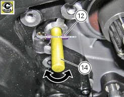
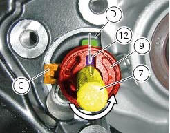
Turn the clutch pushrod (14) counter clockwise until the hole axis of the anti-rotation pin (12) is aligned with the centreline of the casing cover machined surface (d), as shown in the figure.
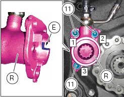
Insert the clutch actuator (r) into the pushrod (14) and bring it fully home on the anti-rotation insert (28).
Note
Upon insertion of the clutch actuator (r), make sure that the tab (c) of insert (28) matches with the actuator slot (e).
Fix the clutch actuator (r) by starting the screws (11).
Note
To bring the clutch slave cylinder (6) internal surface near the casing cover as uniformly as possible, screw and tighten the screws (11) alternatively.
Tighten the screws (11) to a torque of 10 nm +/- 10% (sect. 3 - 3, Frame torque settings), by following the sequence 1 - 2 - 3 - 1.
Positioning of the clutch hose
 Removal of the clutch transmission unit
Warning
The manufacturer of the clutch transmission unit (15) advises
against servicing of its internal parts due to the safetycritical
nature of this component.
Incorrect overhaul of these cri ...
 Hands free
Hands free
Special screw
Plug
Electric fuel plug
Button
Spring
Frame
Elastic pin
Spare parts catalogue
Diavel abs handlebar and controls
Diavel carbon
abs
handlebar and con ...
Other materials:
The hands free module
Introduction
The hands free module incorporates the control unit communicating with the
other nodes on the motorcycle, the on/off
button, the microswitches detecting full lock steering angle (for enabling
steering lock engagement) and the steering lock.
The module is sealed and its individu ...
Removing outer components
Note
The following removal operations are required in order to renew and/or
clean the crankcase halves. If the original
crankcase halves are to be reused, then the removal of these components is not
essential.
Unscrew the screw (17) and remove the oil breather valve (1) with the o-rings
...
Instrument panel on tank
Menu 1 (tot, trip1, trip2, trip fuel).
Menu 2 (cons.Avg., Cons., Speed avg, air and
trip time) if active.
Gear / neutral indication.
Icon referred to the function below from menu 1.
Indication of engine setting for the currently set riding
style.
Currently set riding style (riding m ...