
Ducati Diavel Service Manual: Refitting the cylinder heads pulleys/fixed tensioners
Check that the keyway on the end of the camshaft is in good condition and without burrs.
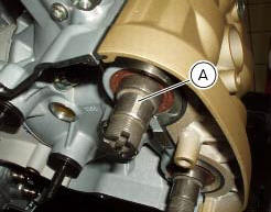
Fit a woodruff key (b) in the keyway of each camshaft.
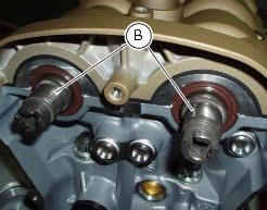
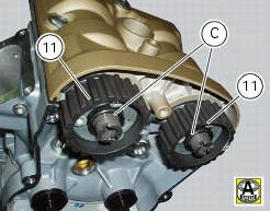
Fit the pulley (11) on the camshaft, inserting the woodruff key in the in the slot (c) in the pulley.
Apply the recommended grease to the threads on the end of the camshaft.
Repeat the procedure on the other camshaft.
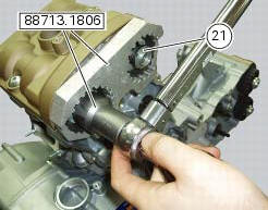
Insert the tool code 88713.1806 Into the pulleys to prevent rotation.
Apply the recommended grease to the mating face of the nut (21).
Fit the nut (21).
Carry out the same operations on the other camshaft.
Important
Always fit new nuts on reassembly.
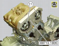
Using the bush supplied with tool with part no. 88713.1806 And a torque wrench, tighten the ring nuts (21) to the specified torque of 71 nm (min. 64 Nm - max. 78 Nm) (sect. 3 - 3, Engine torque settings).
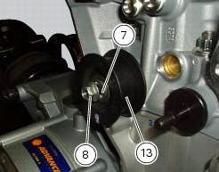
Insert the fixed tensioners (13), with bearings and washers (7), into the cylinder head pins and tighten the nuts (8) to a torque of 25 nm (min. 22 Nm - max. 28 Nm) (sect. 3 - 3, Engine torque settings).
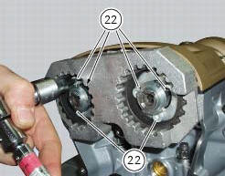
Undo the locking screws (22) of the pulleys, turning them anti-clockwise through 90 +/- 5.
Check that the pulleys have no end float and can rotate freely at all points along the full length of the slots.
 Reassembly of the timing pulleys
Fit the pulley (11) on the flange (24), aligning the timing mark (d) on the
pulley with the timing mark on the (e) on the
flange.
Install the washer (23) up against the pulley, aligning the timi ...
 Refitting the timing belts
Rotate the pulleys on the timing belt driveshaft until the timing mark on the
outer roller is aligned with the mark on the
clutch-side crankcase cover.
In this condition, the horizontal cylinder ...
Other materials:
Refitting the crankshaft/connecting rod assembly
Install the connecting rod assembly (6) and (2) in the crankcase, carry out
the shimming and crankcase half reassembly
procedure as described in sect. 9 - 9.2, Reassembly of the crankcase halves.
Important
Make sure that the connecting rods (2) are correctly positioned in the
cylinders. Incor ...
Instrument panel (dashboard)
The vehicle is equipped with two instrument panels: an lcd
(1, fig. 3) Located on the handlebar containing the key
indications (speed, rpm, coolant temperature and clock) and
a tft colour display (2, fig. 3) Located in the tank fairing
displaying trip information (riding style set, odometer,
co ...
Checking valve clearances
To check the valves clearance, it is necessary to have access to the cylinder
head covers and then remove the
components listed below.
Unscrew the two fixing screws (1) of the cover (2) according to the
crankshaft.
Fit the tool handgrip 88713.0123 In the holes of the generator cover t ...