
Ducati Diavel Service Manual: Refitting the timing belts
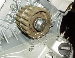
Rotate the pulleys on the timing belt driveshaft until the timing mark on the outer roller is aligned with the mark on the clutch-side crankcase cover.
In this condition, the horizontal cylinder piston will be at top dead centre.
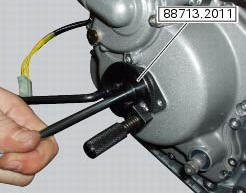
Install in the alternator cover seat the tool code 88713.2011 To prevent crankshaft rotation and lock it with the corresponding pin, tighten the m8 screw of the tool to the torque of 20 nm.
Important
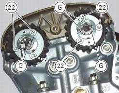
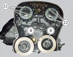
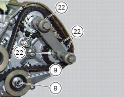
To achieve correct timing, the screws (22) securing the pulleys to the hubs must be loose and positioned in the centres of their slots.
First carry out timing on the vertical cylinder head.
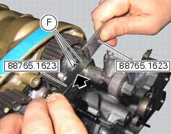
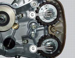
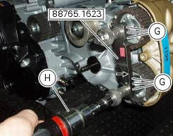
Approach the tool code 88765.1623 To insert the pins (f) in the timing shaft seats (g).
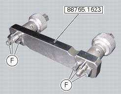
Position the tool code 88765.1623 With legend "up" and the arrow facing the cylinder head cover.
First place the pins (f) of the tool with part no. 88765.1623 In the intake side pulley with the wrench of tool with part no. 88765.1623.
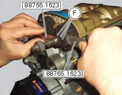
Place the pins (f) of tool code 88765.1623 In the exhaust side pulley manually.
Tighten manually the knobs with tool code 88765.1623 Until they stop.
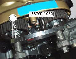
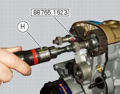
With a torque screwdriver (h) tighten the knob nuts of the tool with part no. 88765.1623 To the torque of 2 nm +/- 10%.
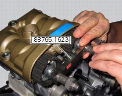
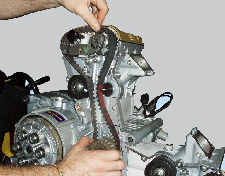
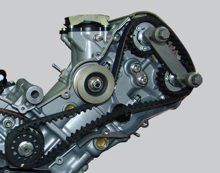
Fit the vertical cylinder timing belt around the camshaft pulleys and pass it behind the idler pulley.
Note
If the used belts are to be refitted, position them in their original direction of rotation and on their original cylinder.
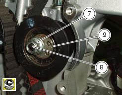
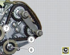
Fit the tensioner pulley (9) and the washer (7) on the pin of the cylinder head.
Apply grease to the tensioner pulley pin threads and to the contact face of the nut (8).
Start the nut (8).
Check the timing belt tension and adjust if necessary as described in the paragraph measuring the timing belt tension values (sect. 6 - 11) Of the vertical cylinder head belt.
Warning
Check the tension on the belt sections (d) and (e) shown in the figure.
Once the required tension has been reached make sure that the nut (8) retaining the tensioner (9) is tightened to a torque of 25 nm (min. 22 Nm - max. 28 Nm) and the screws (22) of the vertical head are tightened to a torque of 10 nm (min. 9 Nm - max. 11 Nm) (sect. 3 - 3, Engine torque settings).
Remove the timing shaft locking tool code 88765.1623 Of the vertical cylinder head.
Carry out timing on the horizontal cylinder head.
Approach the tool code 88765.1623 To insert the pins (f) in the timing shaft seats (g).

Position the tool code 88765.1623 With legend "up" and the arrow facing the cylinder head cover.
Place the pins of tool 88765.1623 In the exhaust side pulley seat (g) manually.
Manually tighten the knobs with tool code 88765.1623 Until they stop.
With a torque screwdriver (h) tighten the knob nuts of the tool with part no. 88765.1623 To the torque of 2 nm +/- 10%.
Fit the horizontal cylinder timing belt around the camshaft pulleys and pass it behind the idler pulley.
Note
If the used belts are to be refitted, position them in their original direction of rotation and on their original cylinder.
Fit the tensioner pulley (9) and the washer (7) on the pin of the cylinder head.
Apply grease to the tensioner pulley pin threads and to the contact face of the nut (8).
Start the nut (8).
Check the timing belt tension and adjust if necessary as described in the paragraph measuring the timing belt tension values (sect. 6 - 11) Of the horizontal cylinder head belt.
Once the required tension has been reached make sure that the nut (8) retaining the tensioner (9) is tightened to a Torque of 25 nm (min. 22 Nm - max. 28 Nm) and the screws (22) of the horizontal head are tightened to a torque of 10 nm (min. 9 Nm - max. 11 Nm) (sect. 3 - 3, Engine torque settings).
Remove the timing shaft locking tool 88765.1623 Of the horizontal cylinder head.
 Refitting the cylinder heads pulleys/fixed tensioners
Check that the keyway on the end of the camshaft is in good condition and
without burrs.
Fit a woodruff key (b) in the keyway of each camshaft.
Fit the pulley (11) on the camshaft, inserti ...
 Refitting the timing covers
Locate vertical cylinder external cover (25), horizontal cylinder external
cover (3) and central external cover (1) by
starting the screws (4).
Apply the recommended threadlocker to the screws ( ...
Other materials:
Removal of the throttle twistgrip
Peel back the rubber sleeve (a) protecting the throttle control cables.
Undo the screws (b) of the throttle grip (6) and open the command.
Disconnect the throttle grip cables (10) by unhooking the cable ends (c) from
their seats.
Remove the throttle twistgrip (6) from the handlebar.
...
Removal of the exhaust system
Remove the silencer, as described in the paragraph "removing the silencer" of
this section.
Loosen the screws (28) and remove the exhaust by-pass valve cover (27).
Turn the exhaust valve pulley (a) to facilitate the throttle cable (25)
output.
Release the end fitting (b) of the cable ...
Removal of the movable tensioner/timing belt
Loosen the nut (8) and remove the washer (7) and the tensioner pulley (9)
from the pin (12) on the cylinder head.
Remove the timing belt (14) from the horizontal cylinder assembly.
Important
If the belts are to be re-used, mark the direction of rotation with an
arrow and also mark the cylin ...