
Ducati Diavel Service Manual: Refitting the cylinder/piston assembly
If new units are used, it is necessary to couple the cylinders and pistons of the same selection (see paragraph "overhaul Of the cylinder barrel/piston components" of this section).
If the pistons have been separated from their cylinders, before reassembling these components, position the piston ring gaps at 120 from one another (the markings must always face the piston crown).
Note
For better sealing the piston ring gaps should be positioned at 180 intervals.
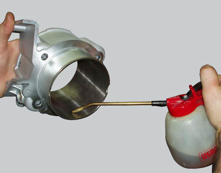
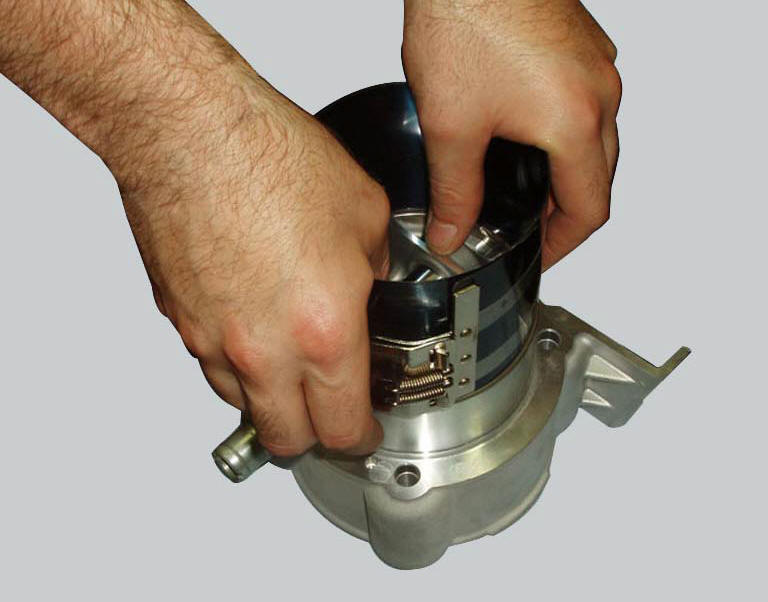
Use a universal tool to carefully insert the piston into the cylinder (first lubricate the inside of the cylinder with engine oil). Position the cylinder with the smallest valve recess is on the side of the exhaust port.
Remove
Remove any deposits and degrease the contact surfaces of the crankcase half and the cylinders.
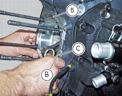
Check for the presence of the cylinders centring dowels (b) and the o-ring (c) on the base.
Apply sealant to the gasket (5) then locate the gasket on the crankcase.
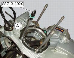
Using the cap 88713.1920, Fit the o-rings (a) on each stud bolt and guide them into their seats in the crankcase.
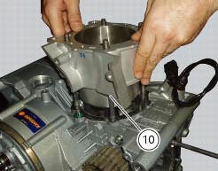
Bring the connecting rod small end close to tdc and slide the barrel-piston assembly (1-10) onto the crankcase studs.
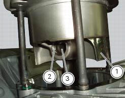
Push the connecting rod small end into the piston close to the gudgeon pin (3) bore. Lubricate and insert the gudgeon Pin.
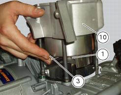
The gudgeon pin (3) must slide smoothly in the connecting rod small end bush and in the piston (1).
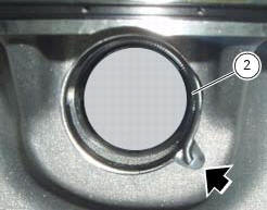
Close the crankcase opening with a cloth to prevent foreign objects from falling inside and then fit the retainer ring (2) as shown in the figure.
Important
Always fit new circlips (2) on reassembly.
Push the cylinder barrel (10) down until it seats against the crankcase.
Refit the bushes (12).
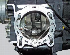
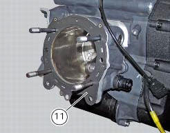
Fit the cylinder head gasket (11) over the studs. The side marked with the part number must be facing the cylinder head.
Note
The shape of the gasket prevents incorrect fitting, provided that the coolant flow holes are aligned with those on the cylinder.
Repeat the procedure for the other cylinder and refit the cylinder heads (sect. 9 - 4.5, Refitting the cylinder head assemblies).
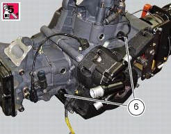
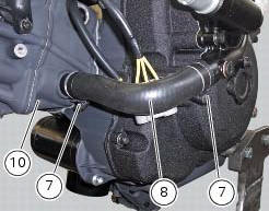
In case they have not been assembled, apply prescribed threadlocker to unions (6) and tighten them to a torque of 25 nm (min. 23 Nm - max. 27 Nm) (sect. 3 - 3, Engine torque settings).
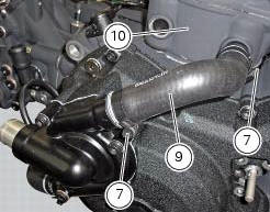
Fit the tubes (8) and (9) and tighten clamps (7) to a torque of 2.5 Nm (min. 2 Nm - max. 3 Nm) (sect. 3 - 3, Engine torque settings).
 Overhaul of the cylinder barrel/piston components
Overhauling the cylinder
Check that the walls of the cylinder bore are perfectly smooth. Measure the
cylinder bore diameter at 50 mm from the top
face and determine the size class to which it belo ...
 Clutch assembly
...
Other materials:
Steering lock on indication
This function informs that the steering lock was turned on.
The steering lock can be turned on during the first 60
seconds after turning off the vehicle by pressing down on the
"run" button.
If the steering lock was enabled correctly, the instrument
panel will show the indication ...
Operations to be carried out by the dealer
List of operations to be performed every 12000 km / year (first
limit reached)
Reading of the error memory with dds on the engine control units,
vehicle and abs
Change the engine oil
Change the engine oil filter
Check and/or adjust valve clearance ( ...
Helmet cable
Note
Helmet cable (2, fig. 104) Can be found inside the tool
kit, see "tool kit and accessories" on page 141.
Pass the cable through the helmet and insert the end of the
cable in the pin (3, fig. 104). Leave the helmet hanging and
refit the seat to hold it in place.
Warning
Th ...