
Ducati Diavel Service Manual: Refitting the lubrication system
Note
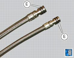
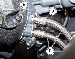
Before fitting the pipes (7), it is recommended to check the presence of the o-rings (e). Lubricate them by using engine oil.
If the nipples (5) have been removed from the radiator insert a washer (6) on each nipple (5) and apply specific threadlocker on threads on the radiator side.
note
The washers (6) must be inserted on the side of the nipples (5) which represent the thread with the smaller diameter, and must be oriented with the cutting edge to the radiator.
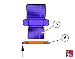
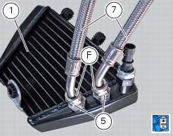
Start the nipples (5) on the oil cooler (1) and tighten them to a torque of 23 nm +/- 10% (sect. 3 - 3, Frame torque settings).
Lubricate the nipples threads (5) with engine oil.
Attach the hoses to the nipples (5), finger-tightening the ring nuts (f) of the hoses on the nipples.
Tighten the ring nuts (f) to a torque of 18 nm +/- 5% (sect. 3 - 3, Frame torque settings).
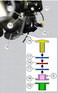
If the horizontal exhaust heat guard assembly was removed, on refitting insert the screw (16) with a washer (17) in heat guard (14) to join it to the exhaust protection (15), and then fit the other washer (17) with spacer (18) on the protruding end of the screw.
Note
The spacer (18) must be oriented with the collar (g) facing the heat guard (14).
Fit the heat guard (14) on the exhaust protection (15) by tightening the screw (16) to a torque of 3 nm +/- 10% (sect. 3 - 3, Frame torque settings).
Fit the heat guard (14) and heat protection (15) assembly on the horizontal cylinder head with support (10) by tightening the screw (11) to a torque of 10 nm +/- 10% (sect. 3 - 3, Frame torque settings).
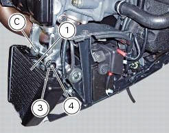
Check that the vibration damper mounts are present on the oil cooler (2).
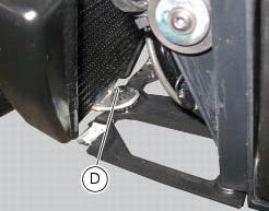
Fit the oil cooler (1) by inserting it first into pins (c) and (d) of the supporting bracket.
If you encounter any difficulties, apply lubricant for rubber to the pin (d).
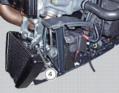
Insert the spacer (3), the screw (4) and start the screw (4).
Position the pipes (7) in the crankcase half. Position the plate (9).
Tighten the screw (8) to the torque of 10 nm +/- 10% (sect. 3 - 3, Frame torque settings).
Tighten the screw (4) to the torque of 6 nm +/- 10% (sect. 3 - 3, Frame torque settings).
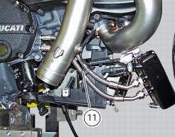
Close the pipe grommet (11).
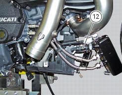
If previously removed, place the sensor (12) with washer (13) on cooler and tighten it to a torque of 19 nm +/- 10% (sect. 3 - 3, Frame torque settings).
Connect the sensor (12) to the main wiring.
 Removal of the lubrication system
Disconnect the sensor (12) of the main wiring.
Open the pipe grommet (11).
Undo the screw (8) and slide out the plate (9).
Slide the tubes (7) out of the half-casing having care not to ...
 Cooling system
...
Other materials:
Injection and ignition
Introduction
Ignition is via a single stick coil per cylinder installed in the spark plug
well. Each thermal unit is supplied by a single
injector, placed under the throttle valve. The amount of fuel injected and the
ignition advances are determined by the
control unit specifically for each c ...
Refitting the front mudguard
Warning
Do not use the motorcycle without the front mudguard fitted to avoid
the risk of the brake pipes fouling the wheel on
braking.
Insert the screws (5) in spacers (6) with recommended threadlocker, as shown
in the figure.
Position the front mudguard (1) and start the special screws (5 ...