
Ducati Diavel Service Manual: Refitting the number plate holder
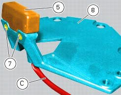
Place the number plate light (5), as indicated, on the number plate holder plate (8) and tighten the screws (7) to a torque of 2 nm +/- 10% (sect. 3 - 3, Frame torque settings).
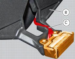
Thread the number plate light wiring (c) into the opening in the number plate holder plate as shown.
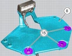
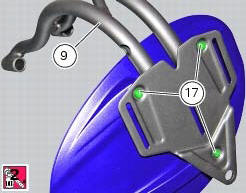
Fit the vibration dampers (15) in the corresponding holes of the number plate holder plate (8). Position the splashguard (16) on the number plate support subframe (9).
Apply prescribed threadlocker on the screw threads (17).
Fix the splashguard (16) by tightening the screws (17) to a torque of 5 nm +/- 10% (sect. 3 - 3, Frame torque settings).
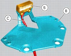
Position the number plate light wiring (c) into the seat in the number plate holder plate (8) as shown.
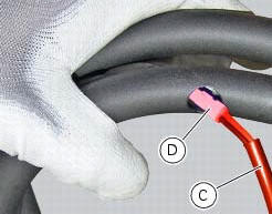
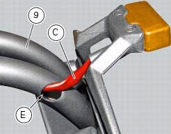
Insert the connector (d) of the number plate light wiring (c) into the hole (e) in the number plate support subframe (9), threading it out of the hole on the opposite side.
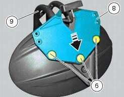
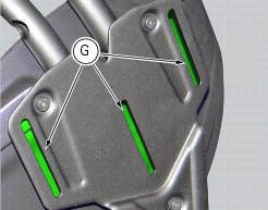
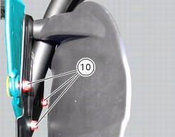
Fit the number plate holder plate (8) to the number plate support subframe (9), fitting the special screws (6) into the vibration dampers and starting the nuts (10) on the opposite side.
Note
Slide the plate (8) along the slots (g) in the subframe (9) until bringing it all the way towards the bottom side.
Tighten the special screws (6) to a torque of 5 nm +/- 10% (sect. 3 - 3, Frame torque settings), by holding the nuts (10) on the opposite side.
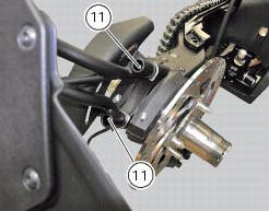
Reposition the assembly on the swingarm and tighten the screws (11) to a torque of 25 nm +/- 10% (sect. 3 - 3, Frame torque settings).
 Removal of the licence plate holder
Disconnect connector (5) of the number plate holder wiring from the main one.
Release the number plate holder light cable from the ties and the cable grommets
as indicated in sect- 7 - 6, fle ...
 Removal of the tail light
Disconnect the connectors (a) and (b) of the tail lights (1) and (13).
Loosen the screws (4) and slide the tail lights (1) and (13) to the rear side;
recover the four spacers (3) and the wash ...
Other materials:
Electric system
Basic electric items are:
headlight:
low beam bulb type: 1xh7 blue vision (12v-55w);
high beam bulb type: 1xh1 (12v-55w);
parking light: led (12v-2.4W).
Electrical controls on handlebars.
Turn indicators:
front: led (13.5V-2.9W).
Horn.
Brake light switches.
Sealed battery, 12v-10 ...
Flexible wiring/hoses positioning
The routing of the abs wiring has been optimised to ensure the minimum
obstruction.
Each section is designed to prevent interference with parts that might damage
wires or cause operating failures when
riding.
Table a
Table b
Table c
...
Refitting the rear brake control
If the pushrod (18), clip (30) and fork (31) assembly has been dismantled,
reassemble it by screwing the nut (29) onto
the rod (18) and then screw the rod into the fork (31) to obtain the measurement
indicated in the figure.
Block the rod and tighten to a torque of 7.5 Nm +/- 10% (sect. 3 - ...