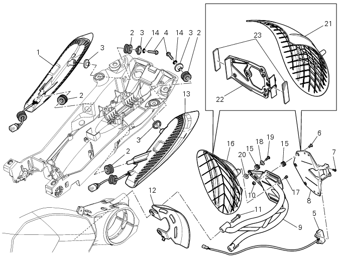
Ducati Diavel Service Manual: Tail light - number plate holder

- Rh tail light
- Vibration damper mount
- Spacer
- Screw
- Number plate light
- Screw
- Screw
- Plate
- Number plate holder
- Nut
- Screw
- Rear chain guard
- Lh tail light
- Spring washer
- Vibration damper mount
- Splashguard
- Screw
- Spacer
- Screw
- Washer
- Splashguard (europe - australia)
- Plate (europe - australia)
- Reflector (europe - australia)
Spare parts catalogue
Diavel abs number plate holder - tail light
Diavel carbon abs number plate holder - tail light
Important
Bold reference numbers in this section identify parts not shown in the figures alongside the text, but which can be found in the exploded view diagram.
- Removal of the licence plate holder
- Refitting the number plate holder
- Removal of the tail light
- Refitting the tail light
 Reassembly of the tool tray
Place the tool tray unit (23) on the lateral brackets (2) and (3) by
tightening the screws (24) to 14 nm +/- 5% (sect. 3-3,
Frame torque settings).
If the handle guide (32) has been previously r ...
 Removal of the licence plate holder
Disconnect connector (5) of the number plate holder wiring from the main one.
Release the number plate holder light cable from the ties and the cable grommets
as indicated in sect- 7 - 6, fle ...
Other materials:
Flexible wiring/hoses positioning
The routing of the abs wiring has been optimised to ensure the minimum
obstruction.
Each section is designed to prevent interference with parts that might damage
wires or cause operating failures when
riding.
Table a
Table b
Table c
...
Removing the electrical components support
Remove the following elements located inside the electrical components
support:
The battery fixing bracket (4) and the battery (14) as specified under
section 6 - 2, battery;
The voltage regulator (3) as specified under section 6 -
2,rectifier-regulator;
The solenoid starter (18) ...
Low hands free key (hf) battery level
The activation of this (amber yellow) "warning" indicates that the hands free
system has detected that the battery that
permits the active key (a) to communicate and turn the vehicle on is almost
discharged.
Note
In this case replace as soon as possible the battery as indicated in sect.
6 - ...