
Ducati Diavel Service Manual: Refitting the oil pump
If removed, apply specific threadlocker on the bushing (7) outer thread, and screw it in the crankcase half, observing the height.
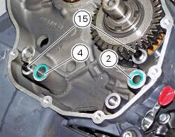
Position the reference bushings (15) and the oil sealing o-rings (2) and (4) according to the crankcase lubrication channels.
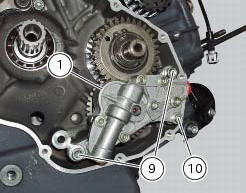
Position the oil pump on the crankcase and tighten screws (9) to a torque of 26 nm (min. 23 Nm - max. 29 Nm) and the screw (10) to a torque of 10 nm (min. 9 Nm - max. 11 Nm) (sect. 3 - 3, Engine torque settings).
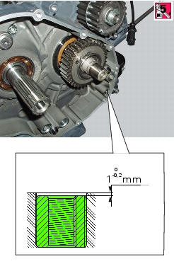
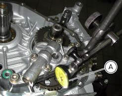
Check the gear clearance with the driving pinion by fixing a dial gauge (a), equipped with the appropriate traces, to the crankcase half.
Position the dial gauge stylus on one tooth of oil pump gear and set the gauge to zero in this position.
Move the gear slightly to measure the backlash; take four readings in diametrically opposed positions of the gear.
The clearance should be 0.10 Mm.
 Reassembly of the oil pump
Check that the circlip (3) and tongue (13) are present on the pump.
Fit the pump drive gear (12) on to the oil pump and secure it by installing the
circlip (6) in its groove.
Insert the by-p ...
 Oil cooler
Oil cooler
Vibration damper mount
Spacer
Screw
Nipple
Aluminium gasket
Oil delivery hose
Screw
Plate
Bracket
Screw
Engine oil pressure sensor
Sealing washer
Heat guard ...
Other materials:
Display background colour (automatic adjustment)
Instrument panel background colour is set automatically
according to exterior lighting conditions.
When sensor detects "poor lighting" (night), it switches to
black background mode; vice versa when a "significant"
lighting is detected (day), it switches to white background
...
Removal of the tail light
Disconnect the connectors (a) and (b) of the tail lights (1) and (13).
Loosen the screws (4) and slide the tail lights (1) and (13) to the rear side;
recover the four spacers (3) and the washers
(14).
...
Reassembly of the tool tray
Place the tool tray unit (23) on the lateral brackets (2) and (3) by
tightening the screws (24) to 14 nm +/- 5% (sect. 3-3,
Frame torque settings).
If the handle guide (32) has been previously removed, position it on the tray
(23) and tighten the screws (34) to 20 nm
+/- 5% (sect. 3-3, Fram ...