
Ducati Diavel Service Manual: Refitting the rear brake calliper
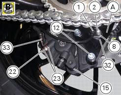
When replacing the brake pipes (33) or removing one of the rear braking system components, pay special attention to the position of the couplings on the pump and the calliper.
Warning
If incorrectly positioned, the hose can affect brake operation and foul moving parts. Position the hose as shown in the figure.
Remember to fit the copper faced sealing washers (23) to the hose end fitting when reconnecting the brake pipe to the brake calliper (15).
After orientating the fitting, lock the special screw (22) to a torque of 23 nm +/- 10% (sect. 3 - 3, Frame torque settings).
If the speed sensor (1) was removed, fit it on the calliper holder bracket (a) with the spacer (8) and the washer (32) and tighten the screw (2) to a torque of 10 nm +/- 10% (sect. 3 - 3, Frame torque settings).
Note
The gap between the sensor (1) and the brake disc fixing screw must be within 0.6 To 2.2 Mm.
If it is necessary to remove the calliper holder bracket (a) in order to refit it, see sec. 7 - 13, Refitting the rear wheel eccentric hub and rear wheel shaft.
Insert the rear brake calliper (15) on the brake disk, aligning it with the holes of the calliper mounting bracket (a).
Grease the screws (12) and tighten to the torque of 25 nm +/- 5% (sect. 3 - 3, Frame torque settings).
In order to fit the pipe (33), the speed sensor (1) and the retaining clamps follow instructions in sect. 7-6, Flexible wiring/hoses positioning.
 Removal of the rear brake disc
Remove the rear eccentric hub (sec. 7 - 13, Removal of the rear wheel
eccentric hub and rear wheel shaft).
Undo and remove the four fixing screws (13) of the brake disk to the wheel axle
and re ...

Other materials:
Battery
Battery safety rules
Warning
Before carrying out any operations on the battery, keep in mind the
safety standards (sect. 1 - 3, General safety rules).
When under charge, batteries produce explosive gases. Keep batteries away from
heat sources, sparks or open flames.
Instructions for use
T ...
Headlight control
This function allows you to reduce current consumption from
the battery, by automatically managing headlight switchingoff.
At key-on, the high beam and low beam lights are off.
When the engine is started, the low beam lights turn on
automatically; from this moment, "normal" operati ...
Disassembly of rear shock absorber - rocker arm - linkage assembly
Undo the screw (15) and remove the rear shock absorber (11) from the rocker
arm (18).
Undo
Undo the screw (14) and the nut (21) and remove the linkages (10) and (12)
from the rocker arm (18).
The rocker arm movement is obtained by needle roller bearings (9) rotating on
a spacer (1 ...