
Ducati Diavel Service Manual: Overhaul of the connecting rods
Make the following dimensional checks on the connecting rods:
- Clearance with gudgeon pin on assembly.
In the event of excessive wear (sect. 3 - 1.1, Crankshaft), replace the connecting rod.
The small end bushing must be in good condition and firmly driven into its seat.
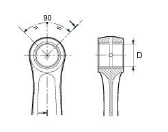
Check for parallelism error measured at 100 mm from the connecting rod longitudinal axis: the value must be h-h less than 0.02 Mm; otherwise, renew the connecting rod.
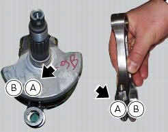
The connecting rod is supplied in two size classes a and b relative to the big end diameter (sect. 3 - 1.1, Crankshaft) as punch marked on the side of the cap.
It is preferable to use crankshafts and connecting rods of the same size class.

Renewal of the small end bushing
To remove the worn bushing, use a suitable punch and a press.
Drill lubrication holes into the new bushing in correspondence with the existing lubrication holes on the connecting rod small end.
Now ream out the bushing until the inside diameter (d) is 20.035 To 20.045 Mm.
Connecting rod bearings
It is good practice to renew the bearings (3) each time the engine is overhauled.
Replacement bearings are supplied ready for assembly and they must not be reworked with scrapers or emery cloth.
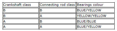
The bearings may belong to two different size classes, each identified by a specific colour (yellow and blue).
The bearings are comprised of an external steel ring, the inner face of which is electroplated with a lead-based compound.
The table shows the appropriate bearings to be fitted according to the size class of the crankshaft and connecting rod.
Crankshaft
The main bearing and big-end journals should not be scored or grooved; the threads, keyways, and slots must be in good condition.
Check for fretting or burrs in the fillet between journal and shoulder.
Fillet radius: 2 mm.
Use a micrometer to measure oval and taper of the crank pin. Measure oval and taper in several different directions.
Use a dial gauge to measure the alignment of the main journals by setting the crankshaft between two opposing centres.
At each overhaul, it is advisable to clean the crankshaft’s internal oilways.
The prescribed values are given in sect. 3 - 1.1, Crankshaft.
The crankshaft is supplied in two size classes (connecting rod pin) a and b, as punch marked on the side of the crank web on the pinion side.
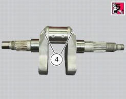
Loosen all crankshaft plugs (4) and (7); heating the crankshaft, if necessary, to remove the threadlocker applied at the time of assembly.
Clean all the oilways using suitable diameter metal brushes and then blow with compressed air to remove any residues that have accumulated and are restricting the oil flow.
Apply prescribed threadlocker to the plugs thread (4) and (7) and then refit them.
Tighten all plugs to a torque of 13 nm (min. 11 Nm - max. 15 Nm) (sect. 3 - 3, Engine torque settings).
Big-end bearing shell-journal clearance
To check the assembly clearance between the bearing shells and crankshaft journals you will lay a strip (a) of green "plastigage pg-1" on the journal. Fit the connecting rod with the original bearings and tighten the screws to a torque of 50 nm.
Remove the connecting rod and compare the thickness of the plastigage strip to the scale (b).
If the width measured corresponding to the existing clearance is not within the prescribed limit (sect. 3 - 1.1, Crankshaft), either the bearings or the crankshaft must be replaced.
 Disassembly of the crankshaft/connecting rods assembly
Unscrew the screws (1) and separate the connecting rods from the crankshaft.
Important
Take care not to mix up components of different connecting rods and
maintain the original orientation.
...
 Reassembly of the connecting rods
Before starting, check that the crankshaft main bearing journals and big-end
journals are free of burrs or evident signs of
machining: if necessary, clean the surfaces with very fine emery cloth an ...
Other materials:
Removing outer components
Note
The following removal operations are required in order to renew and/or
clean the crankcase halves. If the original
crankcase halves are to be reused, then the removal of these components is not
essential.
Unscrew the screw (17) and remove the oil breather valve (1) with the o-rings
...
Renewal of the cooling fan
Loosen the electro-fan retaining screws (15) and (17) and remove the
electro-fan (18) from the radiator.
Carry out the same procedure for the other radiator's electro-fan.
On refitting, position the coolant radiator fan (18) as shown on the fan support
(16), so that the three fan holes mat ...
Abs disabled information not displayed
Fault codes
Dds: displays a fault code described in the description of the abs system.
Dashboard: no fault code displayed.
Wiring diagram
Checks
The abs fault indicator indicates the occurrence of one or more faults in the
antilock brake system, or if the system itself
has been disable ...