
Ducati Diavel Service Manual: Refitting the tail light
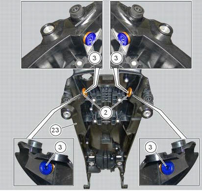
Fit the spacers with collar (3) into the rear vibration dampers (2) located on the gloves compartment (23).
Note
Two spacers (3) must be inserted inside and outside on the right side and two spacers (3) must be inserted inside and outside on the left side.
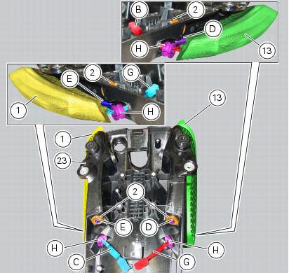
Insert the split vibration damper (h) on the wiring (g) of the left optical unit (13) and the split vibration damper (h) on the wiring (c) of the right optical unit (1).
Note
The usa version uses red optical units (13) and (1).
Fit the left optical unit (13) and the right optical unit (1) on the compartment (23), inserting their pins (d) and (e) into the vibration dampers (2).
Fit the split vibration dampers (h) into the corresponding holes of the compartment (23).
Fit the washers (14) on the screws (4).
Fix the optical units (13) and (1) to the compartment (23) starting the screws (14).
Note
The screws (14) must be inserted into the internal spacers (3) fitted previously.
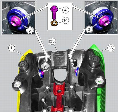
Tighten the screws (4) to a torque of 6 nm +/- 10% (sect. 3 - 3, Frame torque settings).
 Removal of the tail light
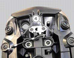
Disconnect the connectors (a) and (b) of the tail lights (1) and (13).
Loosen the screws (4) and slide the tail lights (1) and (13) to the rear side;
recover the four spacers (3) and the wash ...

Other materials:
Removal of the oil pump
Undo and remove the screws (9) and (10) securing the pump assembly.
Remove the oil pump assembly (1) and extract the o-rings (2) and (4) from the
crankcase half together with two locating
bushes (15).
...
High beam flash not working - start/stop lap function not working
Fault codes
Dds: no fault code displayed.
Dashboard: no fault code displayed.
Wiring diagram
Db dashboard connection, s high beam flash button. 7 Orange - o, 1
red/blue - r/b.
Location of connections and components
Location of left hand handlebar switchgear set connection.
Pin ...
Shimming the shafts
Before assembling the crankcase halves, calculate the shims required to
obtain the correct end float of the crankshaft and
gearbox shafts.
To determine the correct shim thickness proceed as follows.
Shimming the crankshaft
After having installed the new main bearings (with bushing (a) or ...