
Ducati Diavel Service Manual: Refitting the filler cap
Position seal (18) in tank cap (10) as shown and reassemble following the removal procedure in the reverse sequence.
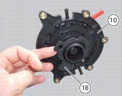
In particular tighten the screws (17) to a torque of 3 nm +/- 10% (sect. 3 - 3, Frame torque settings).
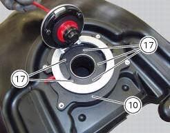
 Removal of the fuel tank filler cap
Remove tank covers (sect. 5 - 2, Removal of the fuel tank fairings).
Remove hoses (8) and (15) from the filler cap assembly (10).
Open the filler cap.
Unscrew the outer screws (17) securing ...
 Replacing the tank flange and fuel sensor
Loosen the screws (19) securing the fuel tank flange (20).
Remove the flange (20) from the tank (20).
Recover the seal (21).
Undo and remove the two fixing screws (g) and move the protectio ...
Other materials:
Refitting the rear wheel
Lubricate the wheel shaft threaded end with prescribed grease.
Insert the wheel shaft by matching (a) with pins (b).
Install spacer (3) with the conical surface faced to the wheel conical
surface, washer (2), apply prescribed grease to nut
(1) and insert it by hand (1).
Tighten the ...
Braking
Slow down in time, shift down to engine-brake first and then
brake applying both brakes. Pull the clutch lever before
stopping the motorcycle, to avoid sudden engine stop.
Abs system
Using the brakes correctly under adverse conditions is the
hardest – and yet the most critical - skill to mast ...
The immobilizer system
For additional antitheft protection, the motorcycle is
equipped with an immobilizer, an electronic system that
locks the engine automatically whenever the ignition switch
is turned off.
The grip of each ignition key contains an electronic device
that modulates the output signal from a special ...