
Ducati Diavel Service Manual: Refitting the clutch master cylinder assembly
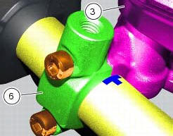
Insert the clutch master cylinder assembly (3) and the clamp (6) on the left handlebar, so that the top mating faces match the mark (z) on the handlebar as shown.
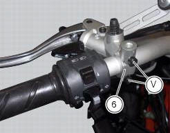
Couple terminal (6) to the clutch master cylinder control and fix them with the screws (v).
Tighten the retaining screws (v) to a torque of 10 nm +/- 10% (sect. 3 - 3, Frame torque settings) following the sequence 1-2-1 starting from the upper screw.
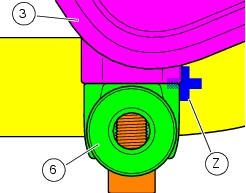
Locate the pipe (4) and seals (2) on the master cylinder assembly (3) and secure it with the special screw (1), without tightening it.
Warning
An incorrectly positioned hose can cause clutch faults and interfere with moving parts.
For the positioning of the clutch hose (4) and retaining clips, see the illustration at the end of this section.
Tighten the special screw (1) to the torque of 23 nm +/- 10% (sect. 3 - 3, Frame torque settings).

 Removal of the clutch master cylinder assembly
Warning
The clutch master cylinder manufacturer advises against servicing of
the clutch master cylinder (1) due to the safetycritical
nature of this component. Incorrect overhaul of this component ...
 Removal of the clutch transmission unit
Warning
The manufacturer of the clutch transmission unit (15) advises
against servicing of its internal parts due to the safetycritical
nature of this component.
Incorrect overhaul of these cri ...
Other materials:
Removal of the water pump
Note
For clarity, the figures show the engine removed from the frame.
Loosen and remove the water pump cover (12) fixing screws (13) to the
generator cover (16).
Remove the water pump cover (12).
Clean the pump housing of any scale. Check the bearings wear by turning the
impeller s ...
Reassembly of the clutch-side crankcase cover
Fit the plug (14) and the gasket (13). Fit the plug (17) and the gasket (15).
If the bush has been replaced, fully seat the new bush (7) in the slot in the
cover using a suitable drift and a press.
If the sealing ring (8) needs to be renewed, fit the new seal into the crankcase
cover, po ...
Frame torque settings
*Dynamic safety-critical point; tightening torque must be within nm +/-5%.
Note
For product specifications and symbols, refer to "product specifications"
(sect. 1 - 2). ...