
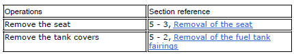
Ducati Diavel Service Manual: Removal of the evaporative emissions canister
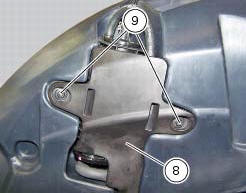
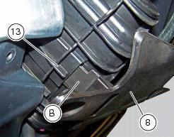
Loosen the screws (9) securing the plate (8) to the tank.
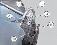
Slightly pull the plate (8) with the canister (13), remove the clamps (3) and (12) and connect hoses (7) and (14).
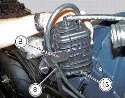
Release the retainers (b) of the plate (8) to remove it from the canister (13).
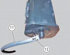
Disconnect the hose (11), removing the clamp (12).
Should it be necessary to replace one or more hoses, follow the procedure outlined in the paragraph "positioning the hoses / clamps and canister filter" of this section to determine the hose routing on the vehicle.
If removed, refit the rubber cover (10) on canister (13) using lubricant specific for rubber.
Fix cover (10) by positioning the tab (c) as indicated.
Introduce the spring (15) inside the hose (11) and reinsert the hose on fitting (d).
Note
The spring (15) must be introduced on the side of hose (11) which will be introduced inside the fitting (d).
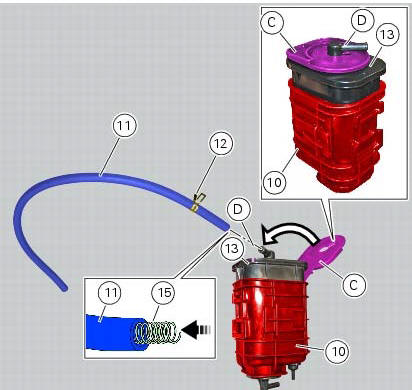
Fix the hose (11) with the clamp (12).
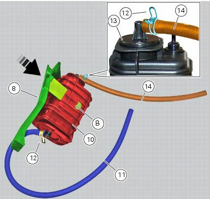
Fit the clamp (7) on the hose (14).
Mount the hose (14) on the upper fitting of the canister (13) and fix the hose (14) by means of the clamp (7).
Fit the plate (8) as indicated by inserting its lateral brackets (b) (on the right and left side) completely inside the slots on the rubber cover (10).
Note
In case of difficulties upon reassembly of the plate (8) we recommend to apply lubricant specific for rubber to the lateral brackets (b).
Place the plate (8) with the relevant canister on the tank and tighten the screws (9) to a torque of 4 nm +/- 10% (sect. 3 - 3, Frame torque settings).

 Evaporative emissions canister system (usa versions only)
Usa models are equipped with an additional system with an evaporative
emissions canister that prevents fuel fumes from
being discharged into the atmosphere.
The breather hose (4) is connected to t ...
 Refitting the evaporative emissions canister
To refit, carry out the removal operations in reverse order, making sure to
locate the hoses as shown in the figures at the
end of the chapter.
Positioning the hoses / clamps and canister filt ...
Other materials:
Frame inspection
Frame
Rh subframe
Lh subframe
Grub screw
Nut
Special screw
Rubber pad
Nut
Special screw
Screw
Left-hand bracket
Hose clip
Hose clip
Right-hand bracket
Special screw
Cover
Handgrab
Slider
Reflector (rear)
Splashguard
Pin
Clip nut
Tool tray
Screw
...
Battery voltage indicator (battery)
This function describes the battery voltage indicator.
To access the function it is necessary to view the ""setting" menu", using
buttons (1) "s" or (2) "t" select the "battery"
function and press the reset button (3) to confirm.
The information will be displayed as follows:
if battery vol ...
Digital rpm indication function
This function displays the number of rpms for improved accuracy when setting
idle rpm.
To access the function it is necessary to view the ""setting" menu", using
buttons (1) "s" or (2) "t" select the "rpm"
function and press the reset button (3) to confirm.
The display shows the numerical v ...