
Ducati Diavel Service Manual: Replacing the tank flange and fuel sensor
Loosen the screws (19) securing the fuel tank flange (20).
Remove the flange (20) from the tank (20).
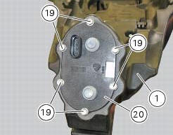
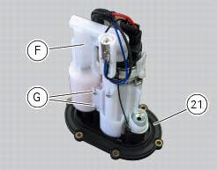
Recover the seal (21).
Undo and remove the two fixing screws (g) and move the protection (f).
Before reassembly, carefully remove any deposits or scale from all parts.
Note
The flange is supplied as a spare part complete with the fuel pump and pressure regulator: the entire flange assembly must be replaced in the event of malfunction.
 Refitting the filler cap
Position seal (18) in tank cap (10) as shown and reassemble following the
removal procedure in the reverse sequence.
In particular tighten the screws (17) to a torque of 3 nm +/- 10% (sect. 3 - ...
 Refitting the fuel tank flange
Insert the flange (20) in its housing in the fuel tank.
Apply prescribed threadlocker to the screws (9) and tighten to a torque of 6 nm
+/- 10% (sect. 3 - 3, Frame torque
settings), following th ...
Other materials:
Instrument panel on handlebar
Lcd.
Neutral light n (green). Illuminates when the gearbox is in neutral.
High beam light (blue).
It turns on to indicate that the high beam lights are on.
Engine oil pressure light
(red).
Illuminates when engine oil pressure is too low. It must turn
on at key-on, but ...
Checking and overhauling the components
Clearance between the clutch drum and friction plates
Insert a friction plate (e) in the clutch drum (f) and measure the clearance
(s) with a feeler gauge.
Clearance "s" must not exceed 0.6 Mm.
If it does, renew the plates and, if necessary, the clutch drum.
Overhaul of the clutch plat ...
Refitting the front sprocket
Grease the o-ring (16) and install it on the front sprocket spacer (15).
Fit the spacer, from the o-ring side, on the secondary shaft and drive it fully
home against the inner ring of the bearing.
Check that the splines of the gearbox secondary shaft and the sprocket are in
perfect condi ...