
Ducati Diavel Owners Manual: Riding mode set indication
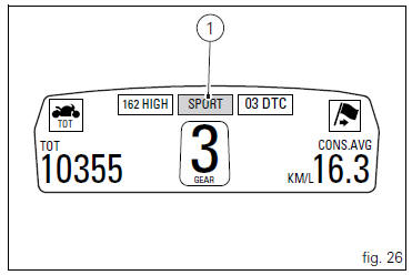
This function indicates the "riding style" set for the vehicle.
Three "riding modes" are available: sport, touring and urban.
Each riding mode can be changed using the "riding mode" function.
 Note
Note
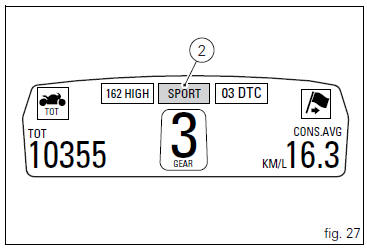
The background of the riding mode (sport, touring or urban) is blue (1, fig. 26) If currently set riding mode parameters are the default ones (ducati factory setting) or yellow (2, fig. 27) If one or more parameters have been modified (customised) by means of the "riding mode" function of the setting menu.
 Engaged gear indicator
This function displays the gears (1, fig. 25).
The instrument panel receives information and indicates the
engaged gear or "n" for neutral.
Note
In the case of a gear sensor "err ...
 Indication if the lap function is active/not active
This function indicates if "lap" function (lap number) is
active.
When "lap" is not lit up, this means that the function has
been switched off.
The "lap" function ...
Other materials:
Trip 1 meter
This function shows the distance travelled since the trip meter was last
reset (in km or miles depending on the specific
application).
Press and hold (1) "s" for 3 seconds while in this function to reset the trip
odometer.
When the reading exceeds 9999.9, Distance travelled is reset and t ...
Riding style function (riding style change)
This function changes the motorcycle riding style.
Each riding style is associated with a different intervention
level of the traction control (dtc - ducati traction control)
and different engine power and output.
To change the motorcycle riding mode, press the reset
button once (12, fig. 1 ...
Lap activation/deactivation function (lap time)
This function activates and deactivates the lap function (lap time).
To access the function it is necessary to view the ""setting" menu", using
buttons (1) "s" or (2) "t" select the "lap"
function and press the reset button (3) to enter the following page.
Function state is highlighted on t ...