
Ducati Diavel Service Manual: Reassembly of rear shock absorber - rocker arm - linkage assembly
Once the needle roller bearings (9) have been removed from the rocker arm (18), upon reassembly fit a new needle roller bearing (9) on drift part no. 88713.1071 And lubricate with recommended grease.
Support the rocker arm and drive the needle roller bearings into the rocker arm bore until the tool seats against rocker arm.
Important
Introduce the needle roller bearings aligned with the hole to avoid any sticking: use a press, if necessary.
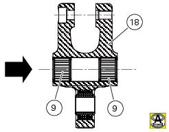
Insert one new seal (8) (with the metallic side faced outwards) into the drift and bring it fully home on the previously mounted roller bearing.
Repeat the above procedure for the other roller bearing (9) and the other seal (8).
Insert the inner spacer (13).
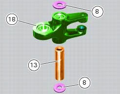
Position the linkages (10) and (12) on the rocker arm (18) by starting the screw (14).
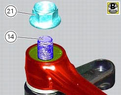
Apply grease to the threaded side of the screw (14) and to the contact face of the nut (21).
Start the nut (21) on the screw (14).
Tighten the nut (21) to a torque of 45 nm +/- 5% (sect. 3 - 3, Frame torque settings).
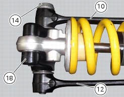
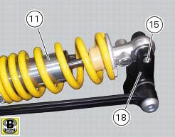
Apply grease to the thread and under the head of the screw (15) that secures the upper part of the shock absorber (11) and insert it in the rocker arm. Tighten the screw (15) to a torque of 45 nm +/- 5% (sect. 3 - 3, Frame torque settings).
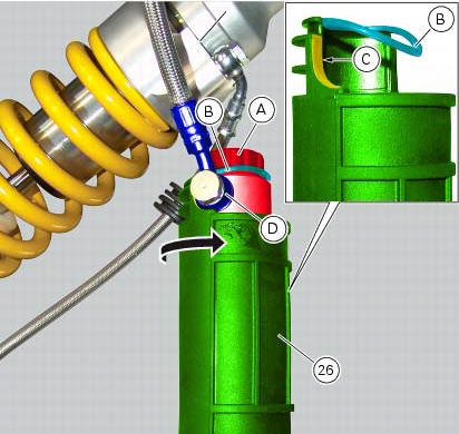
If the shock absorber reservoir covers have been removed, apply lubricant specific for rubber on the inner surface of the rubber cover (26). Fit the cover (26) on the shock absorber reservoir (a) and engage tab (b).
Note
Rotate the cover (26) until face (c) nearly contacts the fitting (d).
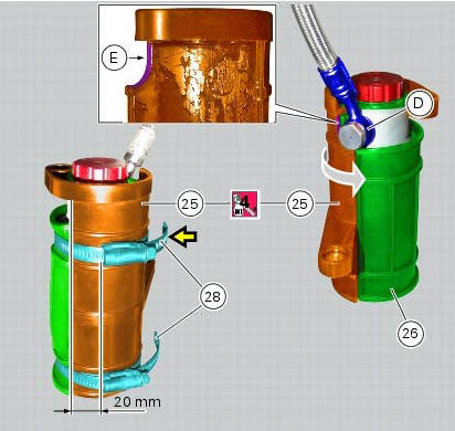
Apply recommended lubricant on the internal surface of the reservoir (25) support.
Position support (25) on the cover (26) and rotate support until face (e) nearly contacts the fitting (d).
Fix cover (26) and support (25) using ties (28), and position the ties so that the external profile of the retainers is about 20 cm away from the edge of support (25).
Note
The top tie (28) (yellow arrow) needs to be fully open in order to be positioned in its seat.
Fit
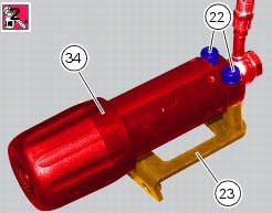
Fit the plate (23) on the preload adjusting knob (34) starting the screws (22) with the recommended threadlocker.
Tighten the screws.
 Disassembly of rear shock absorber - rocker arm - linkage assembly
Undo the screw (15) and remove the rear shock absorber (11) from the rocker
arm (18).
Undo
Undo the screw (14) and the nut (21) and remove the linkages (10) and (12)
from the rocker arm (1 ...
 Refitting the rear suspension
Lubricate the thread and underside of the special screw (1).
Insert the lower side of the shock absorber into the swingarm and insert the
screw (1).
Tighten the screw (1) to a torque of 45 nm ...
Other materials:
General safety rules
Carbon monoxide
When a maintenance operation must be performed with the engine running, maker
sure that the working area is wellventilated.
Never run the engine in an enclosed space.
Warning
Exhaust fumes contain carbon monoxide, which is a poisonous gas that
can cause unconsciousness or e ...
System components
Screw
Abs front speed sensor
Sealing washer
Hose grommet
Abs rear speed sensor
Abs control unit
Front pump - control unit pipe
Control unit - front callipers pipe
Rear pump - control unit pipe
Control unit - rear calliper pipe
Sealing washer
Support
Spacer
Rubber mou ...
Front wheel
Nut
Washer
Left spacer
Sealing ring
Bearing
Front wheel rim
Inner spacer
Screw
Right spacer
Front wheel shaft
Valve
Spare parts catalogue
Diavel abs front and rear wheels
Diavel carbon
abs
front and rear wheels
Important
Bold reference numbers in this section iden ...