
Ducati Diavel Service Manual: Adjusting of the air-gap phonic wheel sensor
(For front as well as rear sensor) in each case of maintenance that foresees:
- Replacement or refitting of the wheel
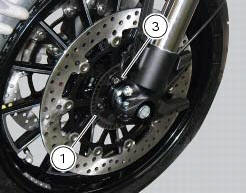
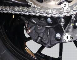
- Replacement or refitting of the phonic wheel (1) or (2)
- Replacement or refitting of the brake discs
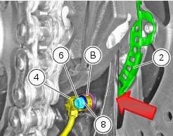
- Replacement or refitting of the speed sensor (3) or (4)
- (Front) replacement or refitting of the sensor holder bracket
- (Rear) replacement or refitting of the calliper holder bracket
It is necessary to check the air-gap between the speed sensor and the phonic wheel, once the components are refitted.
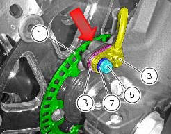
Place the appropriate number of shims (b) under the abs sensor so as to achieve 1.3 To 1.9 Mm air-gap between abs sensor and phonic wheel. When shimming is correct, a 1.3 Mm feeler gauge will fit between abs sensor and phonic wheel, whereas a 1.9 Mm will not.
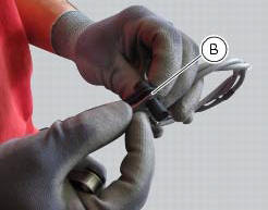
Check at three equally spaced locations (spaced about 120 apart) of the phonic wheels (1) and (2). Shims (b) come in two sizes: 0.2 Mm and 0.5 Mm. Combine the shims as required to achieve correct shimming.
When checking with the 1.3 Mm feeler gauge (go gauge) and the 1.9 Mm feeler gauge (no-go gauge), the abs sensors (3) and (4) must be firmly secured in their seats. This means you need to loosen and retighten the sensor retaining screw fully home with its washer each time you add or remove any shims.
Warning
For the front wheel abs sensor (3), total shims used must never exceed 3 mm on the base version and 3.7 Mm on the carbon version.
For the rear wheel abs sensor (4), total shims used must never exceed 3 mm.
After shimming, tighten the retaining screws (5) and (6) of the sensors (3) or (4) to a torque of 10 nm +/- 10% (sect. 3 - 3, Frame torque settings) placing washers (7) and (8) in-between and check again using the 1.3 Mm feeler gauge (go gauge) and the 1.9 Mm feeler gauge (no-go gauge).
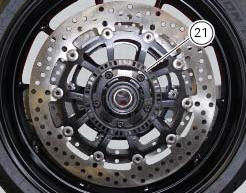
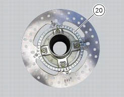
Phonic wheels cleaning
It is important to check that both phonic wheels (21) and (20) are always clean.
Otherwise: gently remove any possible dirt deposits with a cloth or metal brush. Avoid using solvents, abrasives and air or water jets directly on the phonic wheel (21) or (20).

 Bleeding of the abs hydraulic system
If some "sponginess" is detected on the brake control, due to air bubbles in
the system, bleed the system, as indicated in
sect. 4 - 3, Changing the brake fluid.
Before bleeding a brake pump, mo ...
Other materials:
Total distance covered indicator: "odometer"
This function shows the total distance covered by the vehicle (in km or miles
depending on the specific application).
At key-on the system automatically enters this function.
The odometer reading is stored permanently and cannot be reset.
If the distance travelled exceeds 199999 km (or 19 ...
Dashboard system
The vehicle is equipped with two dashboards: an lcd (1) located on the
handlebar containing the key indications (speed,
rpm, engine coolant temperature, and clock) and a tft colour display (2) located
in the tank fairing displaying trip
information (riding style set, odometer, consumption, ave ...
Removal of the swingarm
Before removing the parts in question, you must first carry out the following
operations:
Remove the rear wheel eccentric hub as described in chapter "removal of the
rear wheel eccentric hub and rear wheel
shaft" of this section.
Loosen screws (7) and remove the hose grommets (13), (15) ...