
Ducati Diavel Service Manual: Refitting the primary drive gears and checking backlash
Fully degrease the crankshaft splined end and the corresponding spline on the primary drive gear.
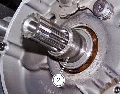
Position the spacer (c) onto the crankshaft.
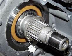
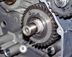
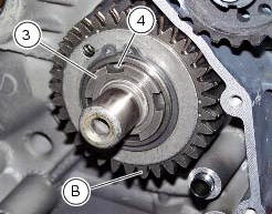
Fit the driving gear (b) onto the crankshaft with the oil pump drive sprocket facing the crankcase.
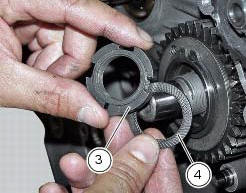
Temporarily secure the gear with the washer (4) and nut (3).
Important
If fitting a new primary driving gear (b), check the backlash.
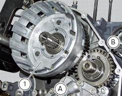
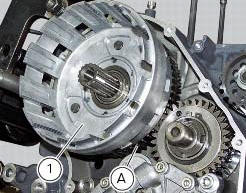
To check the clearance, temporarily fit the clutch bell (1) complete with the primary driven gear (a) on the gearbox primary shaft. Fix a dial gauge to the engine crankcase, positioning the stylus against a gear tooth.
Turn the driven gear (a) to mesh the teeth and check that clearance ranges between 0.05 And 0.07 Mm.
Repeat the check at 16 different points of the driven gear.
If the measured values are outside the permissible tolerance limits, try changing the position of driven gear (a) on the primary shaft, leaving the driving gear (b) on the crankshaft. If still outside tolerance values, renew the whole primary drive gear pair.
After checking backlash, fit the bush 88713.3406 On a torque wrench, lock the pinion (b) with the holding tool 88713.3417.
Position the washer (4) and the ring nut (3). Use the special tool 88713.3406 To tighten the ring nut (3) to a torque of 190 nm (min. 171 Nm - max. 209 Nm) (sect. 3 - 3, Engine torque settings).
Refit the oil pump (d) and check the clearance between the oil pump gear and primary drive gear on the crankshaft (sect. 9 - 2.1, Refitting the oil pump).

Thoroughly degrease the mating surfaces of the clutch bell (1).
Fit the spacer (2) onto the primary shaft. Fit the clutch housing (1) along with the driven gear (a).
 Removal of the primary drive gear
Withdraw the clutch housing (1) complete with driven gear of the primary pair
(a).
Remove the inner spacer (2).
Remove the oil pump (d) (sect. 9 - 2.1, Removal of the oil pump).
L ...
 Gearbox assembly
...
Other materials:
Removal of the fuel tank
On the usa version remove the canister filter as indicated in sect. 8 - 10,
"Removal of the evaporative emissions
canister".
Loosen and remove the front retaining screw (4)
Remove the flange cover (a) by loosening the screws (b), disconnect the
quick-release fittings (c) from the fl ...
Overall dimensions (mm)
Weights
Weight in running order without fluids and battery: 210 kg.
Carrying full load: 400 kg.
Warning
failure to observe weight limits could result in poor
handling and impair the performance of your motorcycle, and
you may lose control of the vehicle.
Important
Do not use addi ...
Checking protection and safety device components
Checking the side stand switch
Remove the switch (1) from the side stand undoing screw (2) and disconnect
the main wiring connector from the switch
(see paragraph "routing of wiring on frame", sect. 6 - 1).
Use an analogue or digital multimeter (sect. 6 - 11, Using a multimeter to check
the ...