
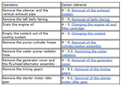
Ducati Diavel Service Manual: Starter motor
Power: 0.7 Kw/12 v
Direction of rotation: counter clockwise viewed from power take-off side.
The starter motor is highly compact and reliable and therefore rarely gives any type of problem. In case of troubles, ensure that the starter motor cable terminal is properly tightened under the nut and shows no oxidation. If the terminal is properly tightened and free from corrosion, remove the starter motor and test it under no-load conditions (no load applied to the shaft). Secure the starter motor to a test bench, making sure you do not damage the casing. Use a fully charged 12 v battery for the test. Use battery-motor connection cables which are no longer than 70 cm and with the same cross-section as the cable on the motorcycle itself. Connect the negative terminal of the battery to an unpainted area of the starter motor casing and the positive terminal to its electrical terminal. The shaft of the starter motor should rotate freely and at high speed. Take care not to short-circuit the two cables connected to the battery.
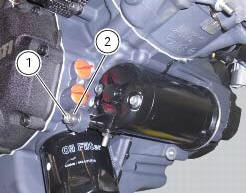
Removing the starter motor
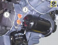
Remove the fixing screw (1) and, if necessary, the insert (2).
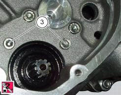
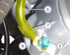
Unscrew the fixing screws (3): the lower screw (3) fixes also the ground cable (6). Collect the toothed washer (7) and the washer (8).
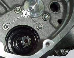

Note
The starter motor retaining screws are assembled with threadlocker.
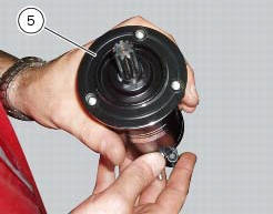
Slide out the starter motor and gasket (5).

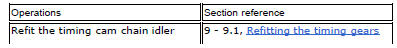
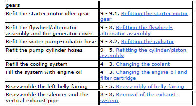
Refitting the starter motor
Inspect the condition of the gasket (5) and renew if necessary.
Position the gasket (5) and the starter motor on the crankcase. Start the retaining screws (3) with recommended threadlocker; the lower one (3) with the ground cable (6), the toothed washer (7) and the washer (8). Tighten the retaining screws (3) to a torque of 10 nm (min. 9 Nm - max. 11 Nm) (sect. 3 - 3, Engine torque settings).
Locate the insert (2) (if removed) in the crankcase half, hand tighten the fixing screw (1) and tighten it to a torque of 10 nm +/- 10% (sect. 3 - 3, Frame torque settings).
Place the starter motor/solenoid starter cable (4) and tighten the retaining nut to a torque of 5 nm +/- 10% (sect. 3 - 3, Frame torque settings).
Important
Fill the cap with protective grease before fitting it on the starter motor.
 Electric starting system
Note
The references of the elements listed below are those of the "wiring
diagram", sect. 6 -1.
Electric starting system
The key components of the electric starting system are a solenoid (6) and ...
 Solenoid starter
Remove the protection cover (a).
Undo the screws (2), taking care to collect the spring washers (3).
Remove the starter motor-solenoid cable (4) and the solenoid-battery cable (5).
Remo ...
Other materials:
Riding mode set indication
This function indicates the "riding style" set for the vehicle.
Three "riding modes" are available: sport, touring and
urban.
Each riding mode can be changed using the "riding
mode" function.
Note
The background of the riding mode (sport, touring
or urban) i ...
Removal of the tail light
Disconnect the connectors (a) and (b) of the tail lights (1) and (13).
Loosen the screws (4) and slide the tail lights (1) and (13) to the rear side;
recover the four spacers (3) and the washers
(14).
...
Indicator cons. - Instantaneous fuel consumption
This function indicates the "instantaneous" fuel consumption.
The calculation is made considering the quantity of fuel used and the distance
travelled during the last second. The datum
is expressed in "l / 100" (litres / 100 km); it is possible to change the units
of measurement for "consump ...